
Setting DC Offset and Bias on an Ayre V-3 After an Output-Stage Repair
Part two of the V-3 rebuild. Part one covered the shorted output MOSFETs, the discontinued IRCP064, and matching the IRFP064 and RFG60P06E substitutes. This one covers the part I promised to split out: actually setting the amp up afterward.
Replacing output transistors in a V-3 is only half the job. The other half is bringing the amp back into alignment — DC offset at the speaker posts and idle current through the output stage — and in this amplifier those two adjustments fight each other. You don’t set one and then the other. You walk them in together, over hours.
Ayre’s own service notes cover both procedures, and they’re specific enough to be worth following exactly. Here’s how it went on the bench, with their numbers.
Before you start
The V-3 runs hot. Not warm — hot. Keep a pair of gloves at the bench, because you’ll be handling a chassis that has been idling in class A for three hours before you’re done.
Know your revision. The bias targets changed partway through production:
| Revision | Minimum | Nominal | Maximum |
|---|---|---|---|
| Rev. A – Rev. J | 500 mA | 550 mA | 650 mA |
| Rev. K – Rev. T | 500 mA | 600 mA | 700 mA |
Those figures are per phase, not per channel. Each channel of a V-3 has two independent output circuits — Ayre calls them phases — one driving each speaker post, and each has its own bias pot. A full channel at nominal is drawing double the number in that table.
Rig the safety net. Bias is measured by pulling the top rail fuse and putting your ammeter across the fuse terminals — I made up a set of leads with fuse-clip ends for this. While you’re in there, drop a 3 A fuse into the lower rail position. If you overshoot the bias adjustment, that fuse is what stands between a slipped screwdriver and a fresh pair of output transistors. The bias pot is very, very touchy.
Use a variac. Parts of this work require bringing the unit up slowly, and after a transistor replacement you want that anyway — the first cold power-up is the moment a mismatched bias spreader announces itself.
Step one: DC offset
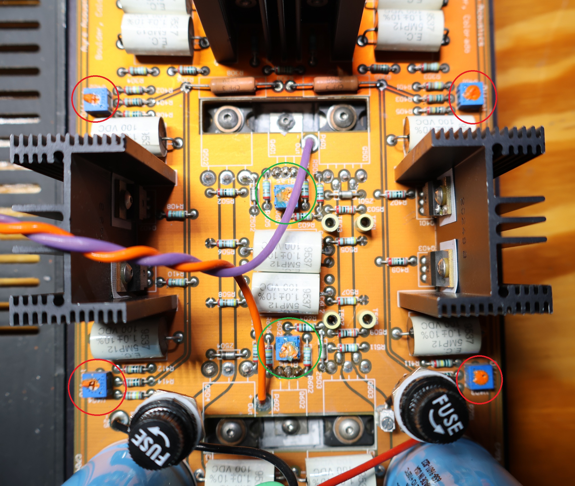
On the image, the DC offset pots (4 pots in total) are highlighted with RED circle.
Do this first, with bias at zero. Setting offset moves bias, so there’s no point in precision-biasing an amp whose offset is still wandering.
1. Get access. Unfasten the channel boards and lay them flat out to the sides of the chassis. You need to reach pots that are inaccessible once everything is bolted back down.
2. Clean the pot-tack. The DC offset pots — V401, V402, V403, V404 — are tacked in place with a compound that has to come off before they’ll turn. Clean all four.
3. Center everything. Set all four pots to their midpoint before powering up.
4. Zero the bias, then come out of standby. DC is swingy in standby, so the unit needs to be in run mode for this. One warning that matters: don’t have both channels sitting at zero bias when you do this. If neither channel is drawing current, too much voltage ends up across some of the supply capacitors. Zero the channel you’re working on, leave the other one drawing.
5. Balance the coupling caps. This is the actual adjustment. You’re balancing the voltage-to-ground at one end of C601 against the voltage at the other end. Something like +2.82 V and −2.75 V is what a balanced cap looks like — you’re not driving either end to zero, you’re making them mirror each other.
Adjust the pot that will be hard to reach once the channel is reassembled — whichever of V401 or V402 ends up buried. The logic here is worth understanding: you’re spending the inaccessible pot’s range now, so that when the boards go back on the chassis, the easy-to-reach pot is still centered and has room to turn either direction for final offset trim.
6. Repeat for C602, adjusting the lower of V403 or V404 by the same reasoning.
7. Tack down the pot you just set with a compound that cures but can be removed later.
8. Reassemble and warm up. Power down, remount the channels, bring the unit up in run mode, and let it cook. Rough adjustments are fine in the first hour; the unit needs at least three hours before you make a final adjustment and tack the pots. This is not a step you can hurry — that’s most of a working day with the amp just sitting there.
9. Alternate channels. Power drawn by one channel affects what’s available to the other. If both channels need adjustment, go back and forth between them rather than finishing one and moving on.
The offset spec
Ayre’s published tolerance is 25 mV at the speaker post with inputs disconnected. But their service guidance is to set it much tighter than that: within 3 mV of zero. The reason is drift, not precision for its own sake — drying pot-tack and hot/cold cycling will de-tune the pot over time, and you want the amp to still be inside spec after it does.
Measure to audio ground, not chassis ground. They’re not the same, and each channel has its own.
You’re done when the channels have held their setting for 15 minutes with no further adjustment. Then tack the pots.
Step two: bias
WARNING: Do it at your own risk as this procedure is very risky and can kill the output MOSFETS (even due to mistracing of the trim pot). If you decide to do it, do it very, very slow. it goes from 0 to 60 mph in a second.
On the image, the bias pots (2 pots in total) are highlighted with GREEN circle.
With the meter in place of the top rail fuse (10 A setting):
- Turn both bias pots on the channel — V601 and V602 — all the way down to zero.
- Flip the front panel switch up to bring the unit out of standby.
- Power up slowly on the variac. Give it a minute to settle in at 120 VAC.
- Slowly bring up V601. Expect nothing to happen at first — you may get as much as half a turn of dead travel before the meter starts to move. Then it climbs. Bring it to 600 mA (or 550 for an earlier revision).
- Now bring up V602 until the whole channel reads 1200 mA.
Here’s the part that catches people out. The two phases share a supply, so the second phase coming on robs the first. What you end up with isn’t 600 and 600 — it’s:
phase 1 = 600 − X phase 2 = 600 + X channel total = 1200 mA
The total is right and the split is wrong. So you balance it:
- Bring V601 back to zero and read the current that V602 alone is producing.
- Calculate the average between that reading and 600 mA, and adjust V602 to hit it.
- Bring V601 back up until the channel total is 1200 mA again.
- Zero V602 and read V601 alone — it should now land near the same average.
Repeat for the other channel if it needs it. As a sanity check, with both phases running the channel total should stay below about 1400 mA.
Step three: go round and round
This is the thing the documentation says plainly and which is easy to underestimate: DC offset affects the bias, and bias affects the offset. Neither procedure is a one-pass operation. You set offset, you set bias, you find the offset has moved, you correct it, you find the bias has moved. You keep circling until both stop drifting — and “stop drifting” means holding for 15 minutes on a fully warmed amp, not looking right for thirty seconds on a cold one.
Between the three-hour warm-up, the alternating between channels, and the iteration between the two adjustments, this is most of a day. Budget for it.
Why this step is the real test after a transistor swap
The signature of a bad set is visible in the first minutes of the first bias adjustment. A correctly matched output pair and spreader will warm up, draw a bit more current for several seconds, and then back off as the spreader picks up the outputs’ heat and pulls the gate-to-gate spread down. A set with a spreader that’s too weak just keeps climbing. That’s thermal runaway starting, and it’s why the 3 A fuse goes in the lower rail position and why the variac is worth the trouble.
Mine settled. Bias came up smoothly, held, and pulled back the way it’s supposed to. Offset came in under 3 mV and stayed there through the warm-up cycle. On the analyzer the rebuilt channel measured the same as the channel I never touched — same power, same distortion, same noise floor.
That’s the whole point of the exercise: not “it works,” but “it’s indistinguishable from the half of the amplifier that was never broken.”