
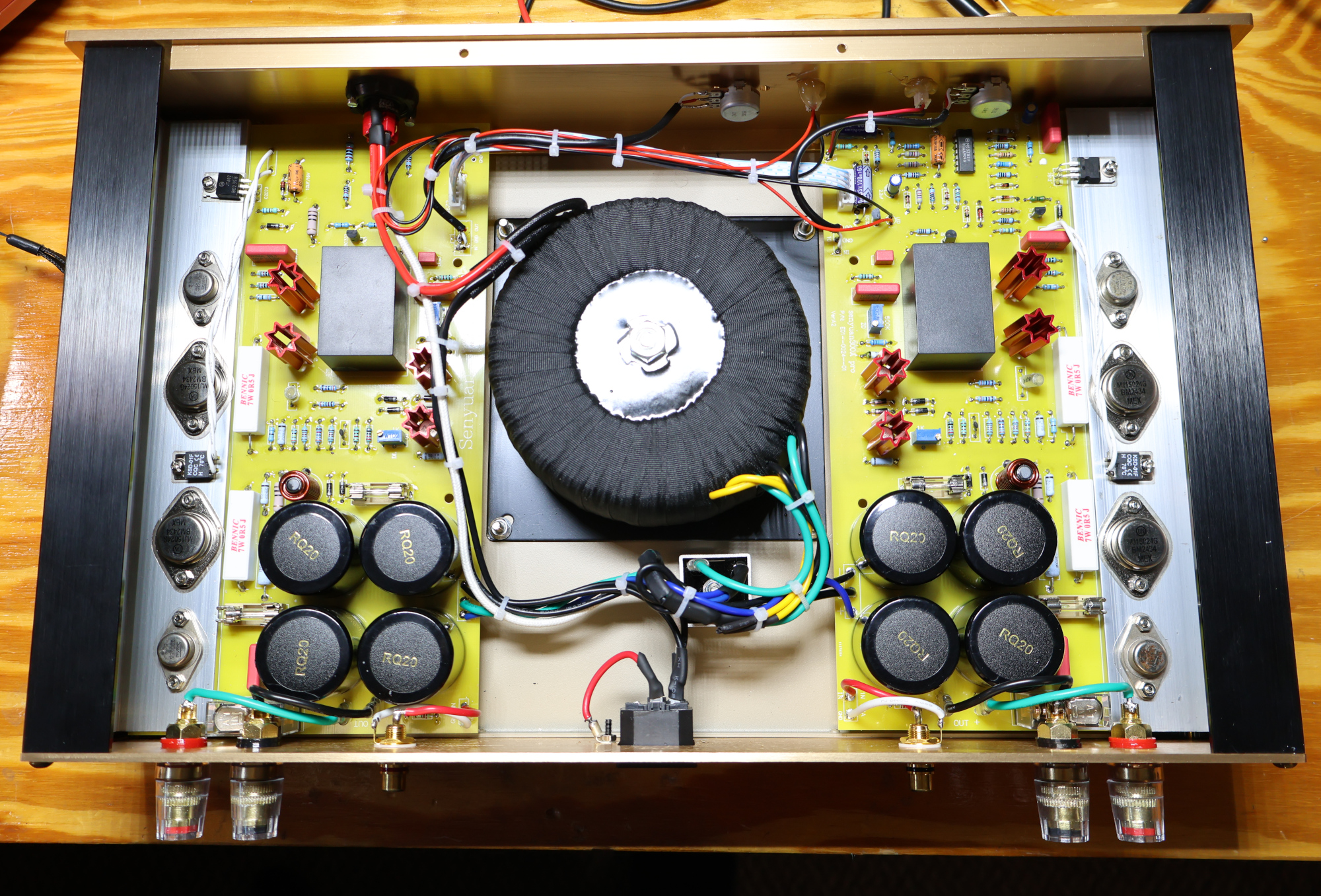
The FM Acoustics FM300A clone (often produced by brands like BRZHIFI or Weiliang) is a popular Class AB clone prized for its classic Swiss-inspired warm, detailed sound profile. Proper calibration of the DC Offset (to protect speakers) and Bias Current / Quiescent Current (to eliminate crossover distortion without thermal runaway) is essential for optimum safety and performance.
Required Tools & Setup Conditions
- Digital Multimeter (DMM): Capable of measuring millivolts (mV) DC.
- Trimmer Tool: Non-conductive plastic or ceramic adjustment tool (prevents accidental shorts).
- RCA Shorting Plugs: (optional) Or short RCA cables with the center pins shorted to shield ground.
- Dim Bulb Tester (DBT): (optional) Highly recommended for initial power-up.
- Warm-up Period: Minimum 15–20 minutes before taking final measurements.
Safety Warning: High voltage AC/DC is present inside the amplifier case. Never touch bare circuit leads while powered on. Ensure speakers are disconnected during all adjustment steps.
1. Preliminary Preparation
- Isolate Inputs & Outputs:Disconnect speakers. Insert RCA shorting plugs into the RCA input jacks.
- Locate Trimpots: On each channel module PCB, locate the multi-turn trimpots:
- DC Offset: Associated with the differential input stage.
- Bias: Integrated into the $V_{be}$ multiplier stage near the output driver transistors.

2. Adjusting DC Offset (Target: 0 mV +- 10 mV)
- Connect the DMM black probe to the Main Speaker Ground Output Terminal and the red probe to the Main Speaker Positive Terminal. Set meter to mV DC mode.
- Power on the amplifier.
- Slowly turn the DC Offset Trimpot ($VR1$) until the multimeter reads as close to 0 mV as possible (+ or – 10 mV is acceptable).
- Repeat for the adjacent channel module.
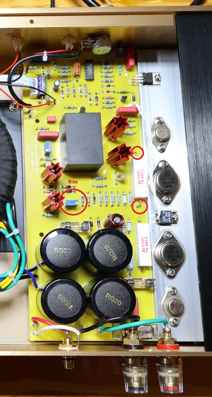
3. Adjusting Bias Current (Target: 15 mV – 25 mV)
Bias establishes the idle current through the output transistors. For the FM300A topology using 0.5 Ohms emitter resistors, a voltage drop of 15 to 25 mV per resistor represents an ideal quiescent bias window (30 to 50 mV).
- Move DMM probes across one emitter resistor on an output power transistor (e.g., Motorola/ONSemi 15024/15025 or original 17419 types).
- Set the DMM to mV DC.
- Slowly turn the Bias Trimpot clockwise to gradually increase the voltage drop. Aim initially for 15 mV
- Monitor the heatsink temperature over 15 minutes. As the amplifier heats up, bias current will naturally drift.
4. Thermal Stabilization & Final Calibration
- Allow the amplifier case to reach operating temperature (approx. 20–30 minutes) with the top cover loosely placed over the chassis.
- Re-check DC Offset and fine-tune back to 0 mV if thermal drift occurred.
- Re-check Bias Voltage across the emitter resistor. Fine-tune Bias so the reading sits stably around 15 to 25 mV
- Touch the heatsinks carefully: they should feel warm to the touch 35-40 C (95 – 105 F), but never hot enough to burn.
Once both channels measure stably, power off the amp, remove the shorting plugs, reattach the chassis cover, and reconnect your system.