
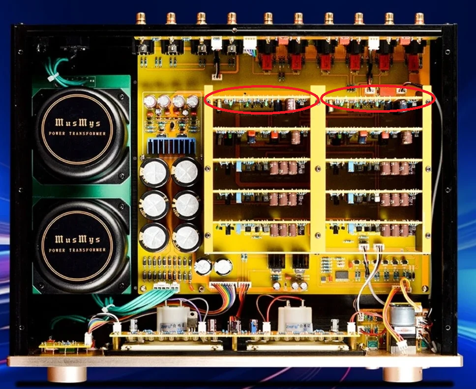
A customer recently brought in a BRZHIFI C-245 Pro preamplifier—a popular clone of the classic Accuphase C-245—asking to address two common issues: excessive overall gain and upgrading the stock operational amplifiers to higher-performance units. Below is a detailed walkthrough covering operational amplifier locations, card removal, gain modification resistor swap, and adjusting the front-panel VU meter sensitivity.
1. Locating and Swapping Operational Amplifiers
The audio circuitry inside the C-245 Pro clone is housed on removable vertical daughter cards attached to the main board via edge connectors.
- Locating the Opamps: Each vertical daughterboard contains dual-channel operational amplifiers mounted in DIP-8 sockets. These opamps handle the input buffer stage.
- Removing the Vertical Cards:
- Unplug the AC power cord and wait at least 5 minutes to ensure filter capacitors fully discharge.
- Remove Screws that hold all the vertical cards.
- Locate the correct card (see image above – red circle)
- Hold the vertical card gently by the top corners using uniform upward pressure.
- Work the card loose from its edge connector without applying excessive rotational force, as this can bend the pins or crack the PCB headers.
- Use an IC puller to remove the stock opamps. Ensure correct pin-1 orientation (notch or dot aligned with the socket mark) when inserting upgrades such as Burson V7
2. Adjusting the Circuit Gain Level
The default gain on the BRZHIFI C-245 Pro clone is too high for modern digital sources with standard 2V RMS outputs, resulting in minimal volume knob travel before reaching uncomfortably loud listening levels.
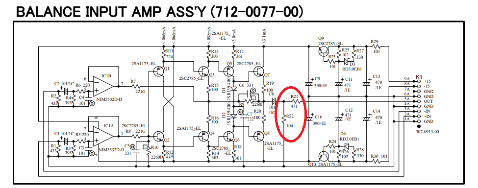
A precise -15 dB attenuation was achieved by physically repositioning the shunt resistor (R22) to sit after the series resistor (R21), ensuring the divider was downstream of the discrete transistor output stage. The successful setup used a 1.8 kΩ series resistor and a 390 Ω shunt to ground, which forced the necessary signal drop without interfering with the unit’s internal unity-gain buffer operation. Perform this changes on both cards for R & L channels.
3. Adjusting VU Meter Sensitivity
When reducing system gain or connecting lower-level source signals, the front-panel VU meters may show very little needle movement. Adjusting their sensitivity restores active visual dynamics. You can do it based on the steps below or just max out the trimmer (by turning it clockwise – that’s what I ended up doing)
- Locating the Meter Driver Circuit: The VU meter driver circuit resides right on the front display harness.
- Trimpot Identification & Calibration:
- Identify the two blue multi-turn trimmer potentiometers (typically labeled VR1 and VR2 or LEFT_VU / RIGHT_VU) situated near the meter driver IC.
- Inject a Test Tone: Play a steady 1 kHz sine wave at standard line level (1V RMS) into the input connectors.
- Adjust Trimpots: Using a non-conductive adjustment tool, turn VR1 (Left Channel) and VR2 (Right Channel) to set the meter needles precisely to the 0 dB mark on the front-panel dial.
- Ensure both channels display symmetrical response across varying volume levels.