
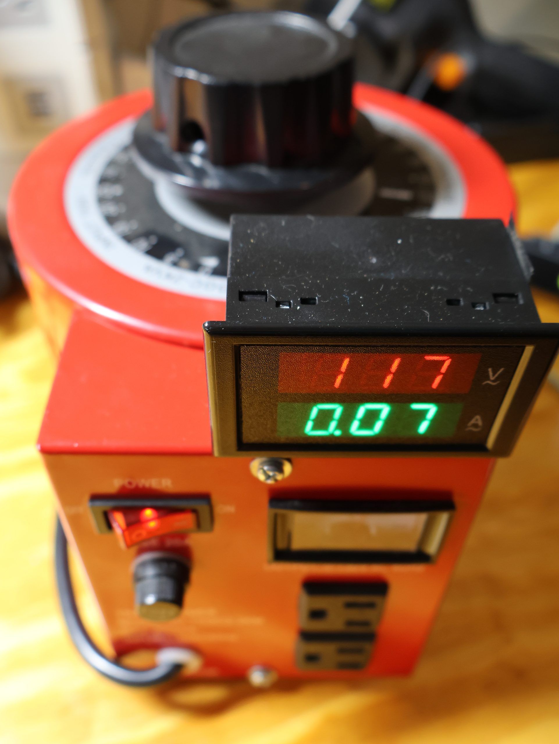
A variac is one of those tools that earns its bench space the first time you bring up a suspect piece of equipment slowly instead of just plugging it in and hoping. Mine is a Beleeb 2000 VA / 20 A autotransformer — a TDGC-2KVA, 110 V in, 0–130 V out. Good iron, decent brush, useful current rating, and one glaring problem: the dial lies.
Not maliciously. It just isn’t a measurement. The printed scale describes the position of the brush, calibrated against a nominal 110–120 V input under no load. My wall sits closer to 122 V some evenings and 114 V on a hot afternoon when the neighborhood air conditioning is running, and an autotransformer is completely unregulated — whatever the line does, the output does, scaled. Add the droop under load (a couple of volts at a few amps is normal, more as you approach the rating) plus ordinary printing and mechanical tolerance on the scale itself, and “the dial says 120” can easily mean anything from 108 to 128 V at the socket.
For dim-bulb testing, gradual power-up of a repaired amplifier, or characterizing something at 90 V versus 130 V, that’s not good enough. And since I spend a lot of time bringing up unknown equipment, I want the second number too: how much current is actually flowing. A device that draws 0.2 A at 60 V and 4 A at 90 V is telling you something important before the smoke does.
So: a cheap panel meter, permanently attached, showing volts and amps at the output.
The meter
I used a combination AC voltmeter/ammeter panel module — the ubiquitous two-color LED unit that shows up under a dozen brand names. Roughly $10, and it ships with the one part that makes it worth buying: an external current transformer.
The relevant specs:
| Voltage range | AC 70–300 V, 45–65 Hz |
| Current range | 0–99.9 A via external CT |
| Accuracy | ~1% ±2 digits |
| Display | Dual 3-digit LED (red volts / green amps) |
| Own consumption | < 0.2 VA |
| CT aperture | ~15.5 mm |
| Panel cutout | ~68 × 38 mm (measure your bezel — vendors disagree) |
Two things about this class of meter matter a lot for how you wire it.
First: the voltage input is also the power supply. There is no separate supply pair. The meter runs on the very circuit it measures, which is exactly why it only starts working at 70 V. Wire the voltage sense to the variac output and the display goes dark below ~70 V — precisely the region where you’re doing your most careful low-voltage bring-up. Wire it to the variac input and it stays lit always, but then it’s reporting your wall voltage, which you already know and don’t care about.
I went with the output, deliberately. Below 70 V the display blanks and I reach for a DMM at the socket; above 70 V — which is where nearly all of my actual testing lives — I get a live readout without touching anything. If that trade bothers you, the fix is a second meter module fed from the input, or a small isolated supply and a meter with a separate supply input. Not worth it here.
Wiring it up
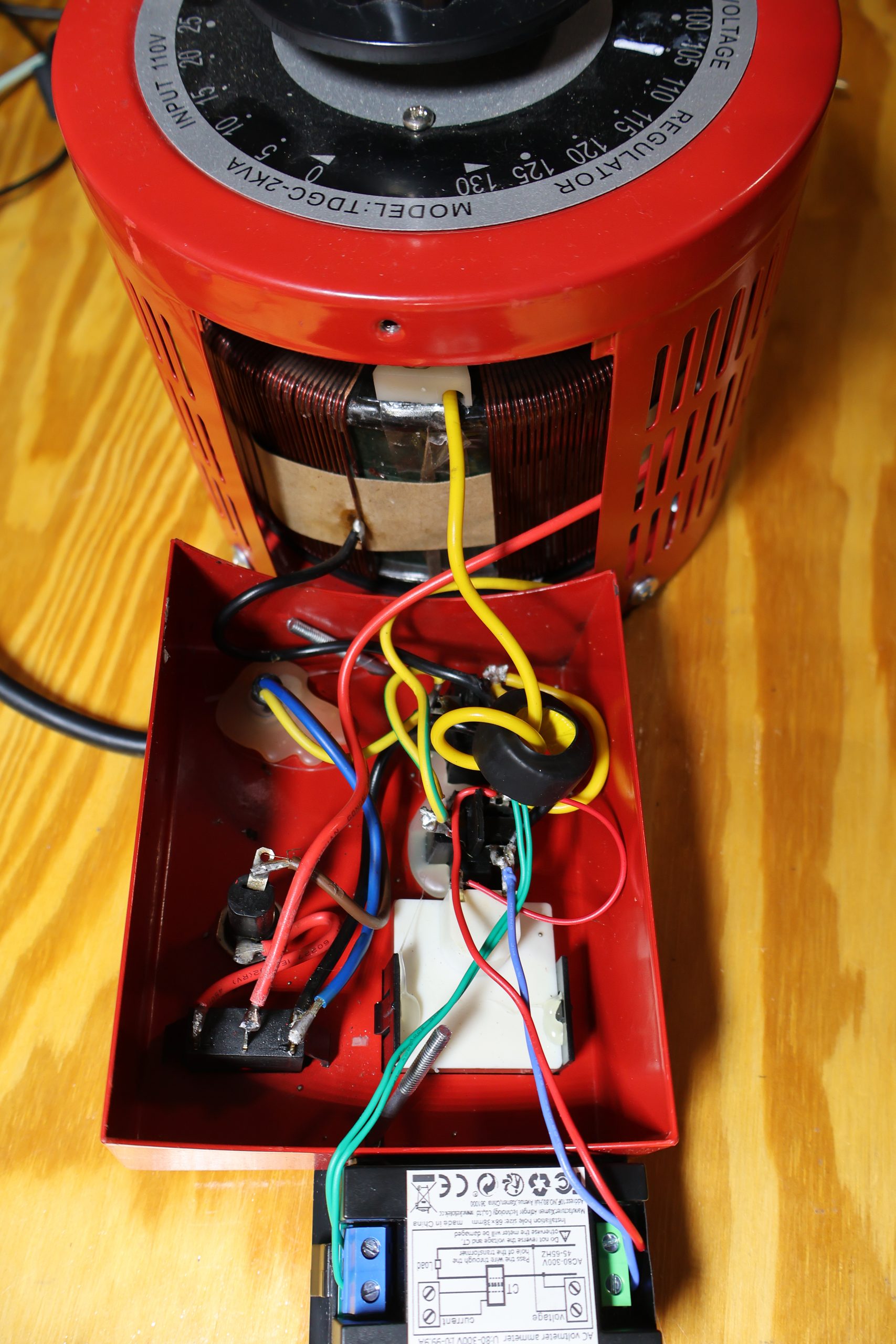
The interior of the variac’s control box is where all the interesting decisions happen. There’s already a rocker switch, a breaker, a pilot lamp, and the output receptacle in there, so the additions were modest:
Voltage sense (red/blue pair). Tapped across the output receptacle terminals — specifically at the socket, not at the brush. That way the reading includes any drop across the switch, the breaker, and the internal wiring, so the number on the display is the voltage your device under test actually sees. It is also downstream of the power switch, which means the meter is genuinely dead when the variac is off rather than glowing at you all night.
Current transformer (green pair). The toroid drops loose in the box; the output hot conductor (yellow here) passes through the ring on its way to the receptacle, and the CT’s two-wire secondary goes to the meter’s current terminals. Note that the CT measures a single conductor — pass both the hot and the neutral through and the fields cancel and you’ll read a permanent zero. That’s the classic first-try mistake.
A trick worth knowing: the CT ratio is set by the number of turns through the aperture. Loop the conductor through twice and the meter reads double the actual current; three times and it reads triple. On a 100 A CT being used to watch a 0.5 A load, that’s the difference between a useless display and a usable one — you just divide in your head. The aperture on this CT is big enough for two or three passes of ordinary 14 AWG easily.
Grounding. The green safety ground goes straight through from the inlet cord to the receptacle ground pin and to the metal chassis, untouched by any of this. The meter doesn’t need it and shouldn’t be in that path.
Everything got soldered and heat-shrunk rather than crimped-and-hoped, because this box lives on a bench, gets picked up, and vibrates.
Mounting
The front panel is already crowded — switch, breaker, lamp, outlet — and cutting a 68 × 38 mm rectangle into it wasn’t happening without relocating something. So the meter went on top of the control box instead: a small opening for the lead bundle, a bracket screw to hold the body, and the display ends up angled toward you when the variac is sitting on the bench at arm’s length. It reads well from a standing position, which is where I actually am when I’m turning the knob.
Results, and what to distrust
Powered up with nothing plugged in, the display settles at 117 V and 0.07 A.
The 117 V is the honest one — that’s my line voltage arriving at the socket with the dial parked at the top of its range, and it’s within a volt of what my DMM says. Confirmed at several dial positions across the range; the meter tracks the DMM closely enough that I’ve stopped bothering to check.
The 0.07 A is the interesting one, and it’s a good illustration of the meter’s limits. On a 100 A CT, 0.07 A is 0.07% of full scale. That is noise, not a measurement — some combination of the variac’s own magnetizing current, CT offset, and the meter’s zero. Treat anything under a few hundred milliamps as unquantified. If you need to resolve a 50 mA standby draw, this is the wrong instrument; use the multi-turn trick above, or a proper low-range shunt.
Two more caveats worth carrying around:
- These meters are almost certainly average-responding, not true RMS. For a clean sine at 60 Hz that’s fine and the calibration factor works out. Feed a rectifier-and-capacitor load — which is to say, essentially every switching supply you’ll ever bring up on a variac — and the current waveform is a narrow peaky mess with a crest factor well above 1.4. The ammeter will read optimistically low. The voltmeter is fine, because the variac’s output voltage is still a sine regardless of what the load does to the current.
- A variac is not an isolation transformer. It’s an autotransformer: the output shares a conductor with the line, and there is a direct connection between your device under test and mains. Adding a meter changes nothing about that. If you need isolation, put an actual isolation transformer in front of it, and keep one hand in your pocket regardless.
Was it worth it?
For about ten dollars and an evening: yes, easily. The dial is now a control, and the display is the measurement, which is how it should have been from the factory. The current readout has already caught one supply pulling far more than it should at half voltage — the kind of thing you’d otherwise discover by ear.
The one change I’d make on a second build is adding a small isolated supply so the meter stays alive below 80 V. Everything else stayed exactly as built.