
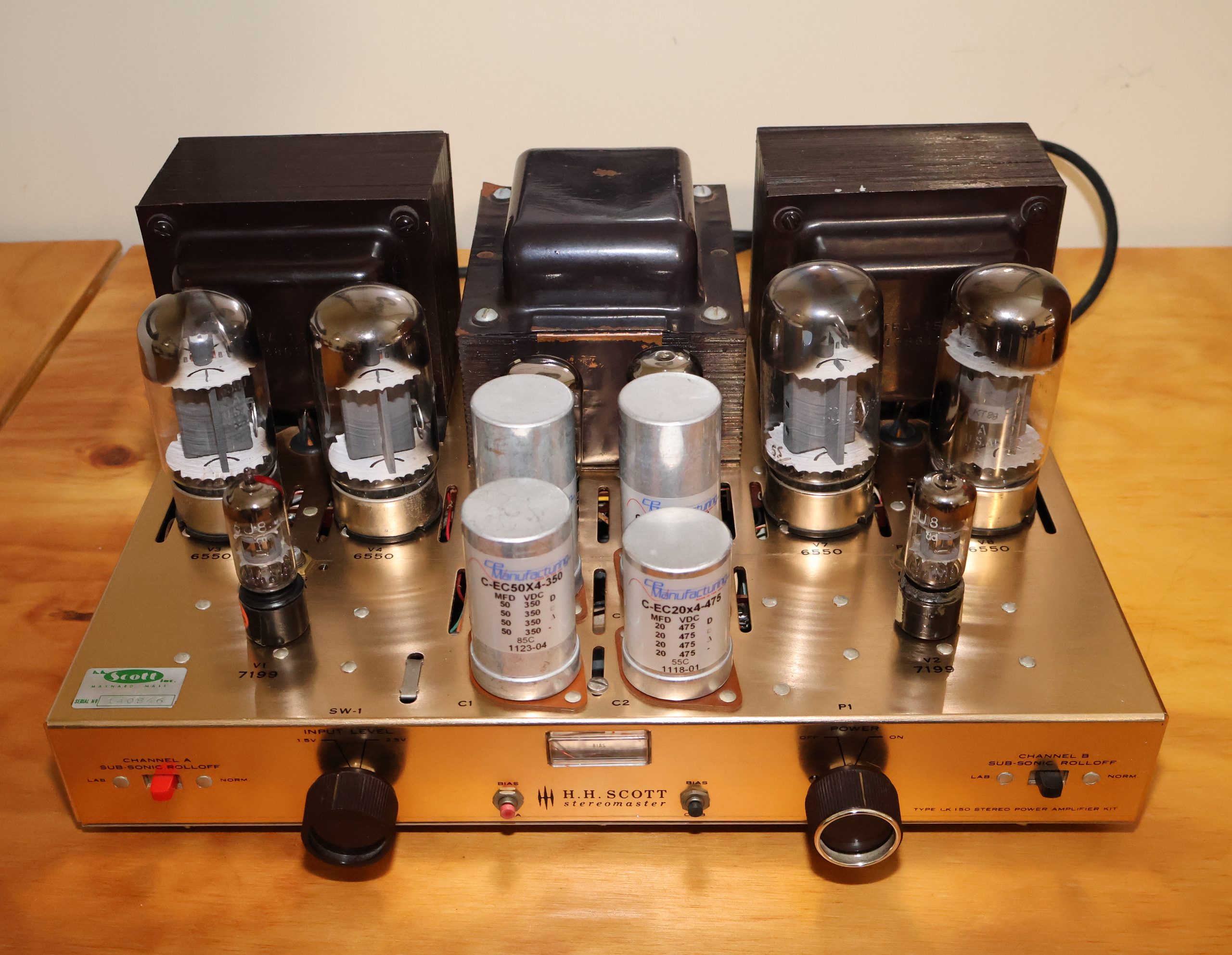
The LK-150 is one of those amps that people underrate because it wore a kit badge. Scott sold it between roughly 1961 and 1964, $170 as a kit and $270 wired, and what you got for the money was a genuinely serious stereo power amplifier: four 6550s, a pair of 7199s, two 5AR4 rectifiers, and output transformers that are physically bigger than what you find in a lot of amps that cost several times as much. Rated output is around 58 W RMS per channel, 130 W total by the marketing math of the day. Sixty-odd years later, the iron is almost always fine and everything made of paper, electrolyte, or aluminum is not. That is the whole restoration story in one sentence.
The topology, and why it matters before you touch anything
The LK-150 signal path is short. Per channel there is exactly one small-signal bottle, a 7199, which is a pentode and a triode in one envelope. The pentode section does the voltage amplification, and the triode section following it acts as the split-load (cathodyne) phase inverter, producing the two antiphase drive signals for the output pair. From there it goes straight into a push-pull pair of 6550s per channel, and out through the transformer. No cathode follower drivers, no long-tailed pair, no extra gain stages to cover up for a mediocre output stage. Scott could get away with that because the output transformers are good enough to take a modest amount of global negative feedback without the loop getting ugly.
A few consequences fall directly out of that design, and they shape how you restore it:
- One tube per channel means one 7199 does everything up front. A noisy, gassy, or unbalanced 7199 is heard as hum, imbalance, or hardness that no amount of recapping will fix. 7199s are also long out of production and getting silly in price, which is worth planning for before you start; the RCA black plates are the ones everybody chases, and there is a cheaper way around the problem covered further down.
- A split-load inverter has very little gain and a fairly high output impedance on the cathode side. It does not like being loaded with sloppy, lossy coupling capacitors, and it does not like leaky ones at all.
- The output stage is fixed bias, with an adjustment trim pot and test point per channel. Fixed bias is what lets 6550s make real power at low distortion, but it also means the tubes have no cathode resistor holding them back. If the bias supply sags or a coupling cap leaks DC onto a control grid, the output tubes go into thermal runaway and red plate. On a cathode-biased amp that is a bad afternoon; here it can cost you a transformer.
- Rectification is by two 5AR4s, and they are not one per channel — they are wired in parallel, feeding a single B+ supply that both channels share. Scott did this because one 5AR4 simply cannot pass the current four 6550s demand. Two in parallel split the load, each tube runs at half the current and therefore cooler and with less voltage drop, and the pair between them can handle a turn-on surge that would cook a single rectifier. It also means the two tubes should be treated as a set: fit them as a matched or at least similarly-aged pair, because if one is noticeably stronger it will hog the load and wear out first, and replace both at the same time. The flip side of a shared supply is that both channels draw from the same reservoir, so supply impedance is a channel-to-channel crosstalk path as well as a hum path — another reason the filter capacitors matter more here than they would in a dual-mono design.
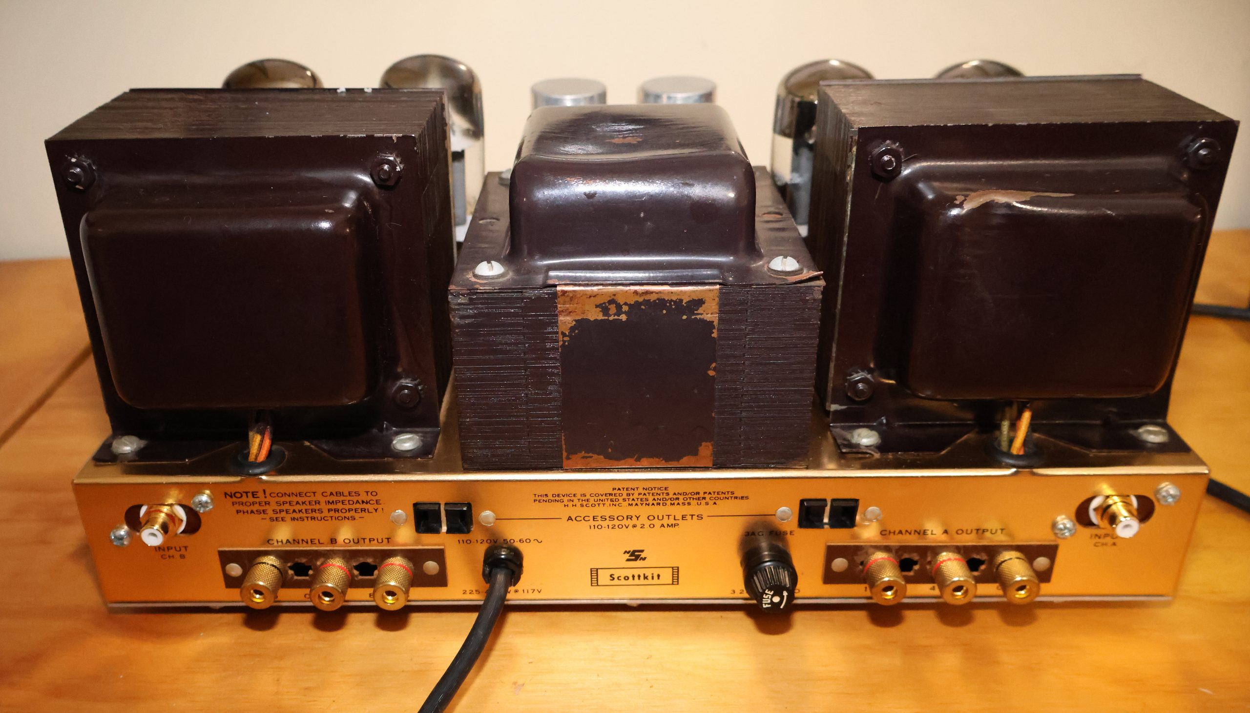
- The output transformer brings out 4, 8, and 16 ohm taps plus common, which is exactly what makes the speaker terminal situation on this amp interesting (more on that below).
So the restoration priorities write themselves: get the power supply solid, get every coupling cap out of the amp, make the bias supply reliable and adjustable, then worry about connectors.
Main power supply capacitors
Every original can capacitor in this amp is now more than sixty years old, and none of them are worth arguing about. Even the ones that measure roughly correct on a meter have lost most of their ability to handle ripple current, and a can that has gone high-ESR shows up as hum, as mush in the bass, and as B+ that sags whenever the amp is asked to do anything.
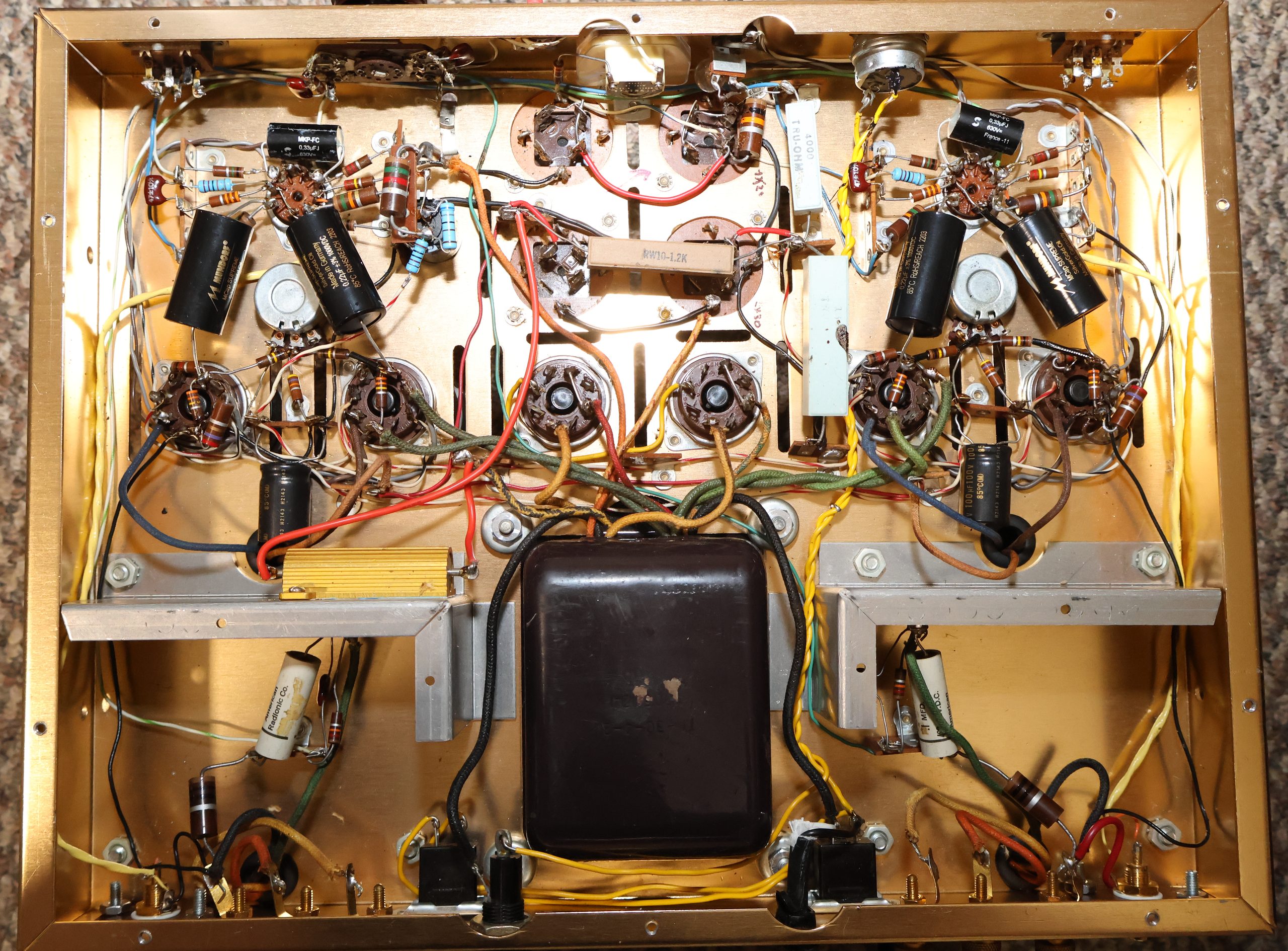
I went with new multi-section cans from CE Manufacturing rather than restuffing or hanging modern radials under the chassis. They are made on the old Mallory tooling, they mount in the original holes with the original clamps, and the amp still looks like an LK-150 when you are done. The specific parts:
- Rear two cans: C-EC30X3-525, three 30 µF sections rated at 525 V. These are the reservoir/first-filter positions right behind the rectifiers, where the working voltage is highest and the ripple current is worst. The 525 V rating matters here, not because the amp runs that high in normal operation, but because B+ climbs well above its steady-state value during warm-up, before the output tubes start drawing current. Sizing to the running voltage instead of the cold-start voltage is the classic way to kill a new capacitor within a year.
- Front two cans: C-EC50X4-350, four 50 µF sections at 350 V, and C-EC20X4-475, four 20 µF sections at 475 V. These handle the lower-voltage nodes downstream: screen supply, driver stage supply, and the decoupled feeds for the small-signal circuitry.
One benefit worth calling out: no more series-connected sections. Scott, like everybody else building to a price in 1961, was working with capacitor sections whose voltage ratings were marginal for the B+ this amp develops, so part of the filter bank was wired as two sections in series, with balancing resistors across them to keep the voltage split even. That trick works, but it costs you twice over. Two equal sections in series give you half the capacitance of one of them, so a pair of 40 µF sections buys you 20 µF of actual filtering. And it puts one capacitor body up at roughly 450 V above ground rather than at ground, which stresses the can’s insulation, makes the balancing resistors a permanent failure point, and means a drifting resistor quietly shifts the voltage split until one section is over its rating.
The new cans are rated high enough to take the full node voltage on their own, so the series stack goes away entirely. Each section now sits with its negative end at chassis ground where it belongs, the balancing resistors come out of the circuit, and the capacitance that the series connection was halving comes back. The net result is more effective filtering than the amp left the factory with, from parts that are working well inside their ratings instead of right at the edge of them. Because the recovered capacitance is a modest increase on nodes that are downstream rather than a huge slug dumped straight onto the rectifier’s input — and because there are two 5AR4s in parallel sharing whatever surge does occur — the rectifiers are not asked to do anything they were not designed for, and turn-on behaviour stays where it should be. That is the ideal kind of restoration change: better performance and better reliability at the same time, with no fight over which one you would rather have.
A few notes on doing this job that are worth more than the part numbers:
- Photograph everything before you unsolder it, and mark which can lug goes to which node. The sections in a multi-section can are not interchangeable, and the tab arrangements on the replacements are not always in the same order as the originals.
- Resist the urge to massively over-specify capacitance beyond what the series-to-parallel change gives you. The 5AR4 has a maximum input-capacitance spec for a reason, and while running two in parallel does buy you some headroom against it, piling modern radials onto the first filter node still shortens rectifier life and raises turn-on stress. Recovering the capacitance the series arrangement was throwing away is free; going well past it is not.
- Do not cut the old cans out and leave them dangling as decoration wired to nothing without checking the chassis ground path first. The can bodies are the ground reference for those nodes; if you replace them, the new can needs the same solid connection to the same point, or you get hum you will chase for weeks.
- Check the bleeder resistors while you are in there. Bleeders drift high or open entirely, and with the amp off and new caps that hold charge properly, an open bleeder means several hundred volts sitting on the supply long after you have pulled the plug. Replace them, and still verify with a meter before you put your hands in the chassis. Every time.
- After the recap, bring the amp up slowly on a variac or a dim-bulb limiter, with no output tubes in the sockets on the first pass, and watch the B+ come up. That first power-up is where a misplaced can lug announces itself, and you would rather it announced itself at 60 V than at 500 V.
The improvement from the supply work alone is not subtle. Hum floor drops, the bottom end firms up, and the amp stops getting congested when it is asked for real level.
Coupling capacitors
The originals are wax/paper types, and in a fixed-bias amplifier they are not just a sonic question, they are the single most common cause of a dead output tube and a burnt output transformer. As paper caps age they become slightly conductive, and a coupling cap feeding an output grid that leaks even a fraction of a volt of DC will drag that grid positive, raise idle current, and set the tube on the runaway path. Any of them still in the amp should come out on principle, whether or not the amp sounds fine today.
I replaced them with Mundorf Silver/Gold Oil. These are the nicest-sounding coupling caps I have used in an amp of this type: very smooth and transparent, with real resolution, but without stripping out the midrange bloom that is the whole reason to own a 6550 amp with big iron in the first place. A lot of modern film caps make a vintage amp sound faster and more detailed by making it sound thinner and more etched. These do not do that. Keep the values the same as original, keep the voltage rating comfortably above B+, and keep the leads short and dressed away from the AC wiring, because oil caps are physically large and it is easy to end up with a lead running past the power transformer where it will pick up hum.
The bias circuit
This was the part that needed actual thinking rather than shopping. The LK-150’s negative bias supply is rectified by a single germanium diode, and on this amp it had given up. Germanium diodes fail gradually and dishonestly: they go leaky, the bias voltage becomes less negative, idle current creeps up, and the amp appears to work right up until the moment it does not.
I replaced it with a 1N4007, and it worked out nicely. The silicon part has a higher forward drop than germanium, roughly 0.7 V versus 0.3 V, so the bias supply comes out a few tenths of a volt different from stock. In an amp with a fixed bias divider that would matter. Here it does not, because Scott provided per-channel trim pots for exactly this kind of adjustment, and the range is wide enough that the difference disappears into the pots. The 1N4007 also brings 1000 V of reverse rating and essentially no leakage, so this is one of the few places where the modern part is straightforwardly better than the original rather than merely equivalent.
The electrolytics in the bias supply all had to go as well, and they deserve more respect than they usually get. They are small, cheap, low-voltage parts sitting in a corner of the chassis, and they are the ones that will destroy your output tubes. If a bias filter cap goes open or high-ESR, the negative supply becomes ripple-riddled or collapses, and the output stage takes the hit. Replace them all, observe polarity carefully since this is a negative supply and it is easy to get backwards, and use decent 105 C parts.
Once it is back together: set bias with the amp warmed up for at least fifteen or twenty minutes, per the test points and target in the manual, then come back and check it again after an hour and again after a few days of use. New output tubes drift as they settle in, and a fixed-bias amp that has just had its bias supply rebuilt deserves a couple of follow-up checks before you stop paying attention to it.
The 7199 problem, and the 6BL8 workaround
The one genuinely awkward part of owning an LK-150 in this century is the driver tube. The 7199 has not been made in decades, demand from Dynaco ST-70 owners keeps the remaining stock moving, and prices have gone from annoying to absurd. You need two good ones, and a matched, quiet pair of NOS black plates can now cost more than people paid for the whole amplifier.
The practical answer is a 6BL8 (the European designation is ECF80) on an adapter. It is the same basic species of tube, a triode and a pentode sharing one nine-pin envelope, and it is still plentiful and cheap because it was made by the million for television service. What it is not is a drop-in: the pin assignments are completely different from the 7199, which is exactly why the adapter exists. A good adapter is just a small socket-and-plug sandwich that reroutes the pins, so nothing in the amp gets modified and the change is entirely reversible if you find a pair of 7199s at a price you can live with.
Sonically it is not a downgrade, which surprises people. It is a slightly different flavor rather than a lesser one, and given the price difference you can afford to buy several pairs and pick the quietest, which is a luxury nobody gets with 7199s any more. You can experiment with tubes from Amperex, Telefunken, Brimar, Mullard, etc. What not to like?!
Other triode-pentode types get used for the same job in similar circuits, the 6U8A/ECF82 and 6GH8A among them, each with its own adapter wiring. The 6BL8 is my preference here on sound quality and price, but the general point stands: this is a solved problem, and it is not worth paying 7199 money unless you specifically want the original tube in the original socket.
Speaker terminals
The original speaker connections are the usual early-sixties screw-terminal strip, which is fine for bare wire and useless for anything else. I replaced them with proper 5-way binding posts, and here is where the transformer taps come back into the story: there are four connections per channel, common plus 4, 8, and 16 ohms, and only three binding posts will physically fit in the space the original strip occupied. Something had to go, so I abandoned the 16 ohm tap and kept common, 4, and 8.
That is a compromise I would make again. Sixteen ohm speakers were common when this amp was built and are close to extinct now; if you own a pair, you already know it, and running them off the 8 ohm tap costs you some power and a slightly higher effective output impedance rather than causing any harm. If you do want to keep all four taps, the alternative is to move to a small terminal plate mounted on a modified rear panel, which is more work and less original-looking.
Input jacks
The original input connectors are aluminum, and aluminum is a poor material for a signal connection. It oxidizes, and aluminum oxide is an insulator, so the contact resistance climbs over decades and you get intermittency, crackle, and a channel that drops out when you wiggle the cable. They are also mechanically loose by modern standards and will not grip a decent RCA plug. I fitted modern gold-plated RCA jacks, which solves all of that at once, and made sure the grounding scheme stayed the same as original rather than accidentally introducing a second ground path through the chassis, which is a very easy way to invent a hum loop while you are trying to fix one.
Where it ended up
Rebuilt this way the LK-150 is a genuinely great sounding amplifier. It still sounds like a tube amp, which is the outcome you want. The supply and bias work is what makes it reliable, the Mundorfs are what make it transparent, and the connector work is what makes it pleasant to live with. Everything else, the iron and the topology, Scott got right in 1961.
Two closing cautions. This amp holds lethal voltage on capacitors that are now brand new and much better at holding it than the ones you removed, so discharge and verify before every session inside the chassis. And do not power it up after a recap without a current limiter of some kind and a plan for what to look at first. The LK-150 is worth restoring properly, and it is very much worth not letting one mistake take out an irreplaceable output transformer.