
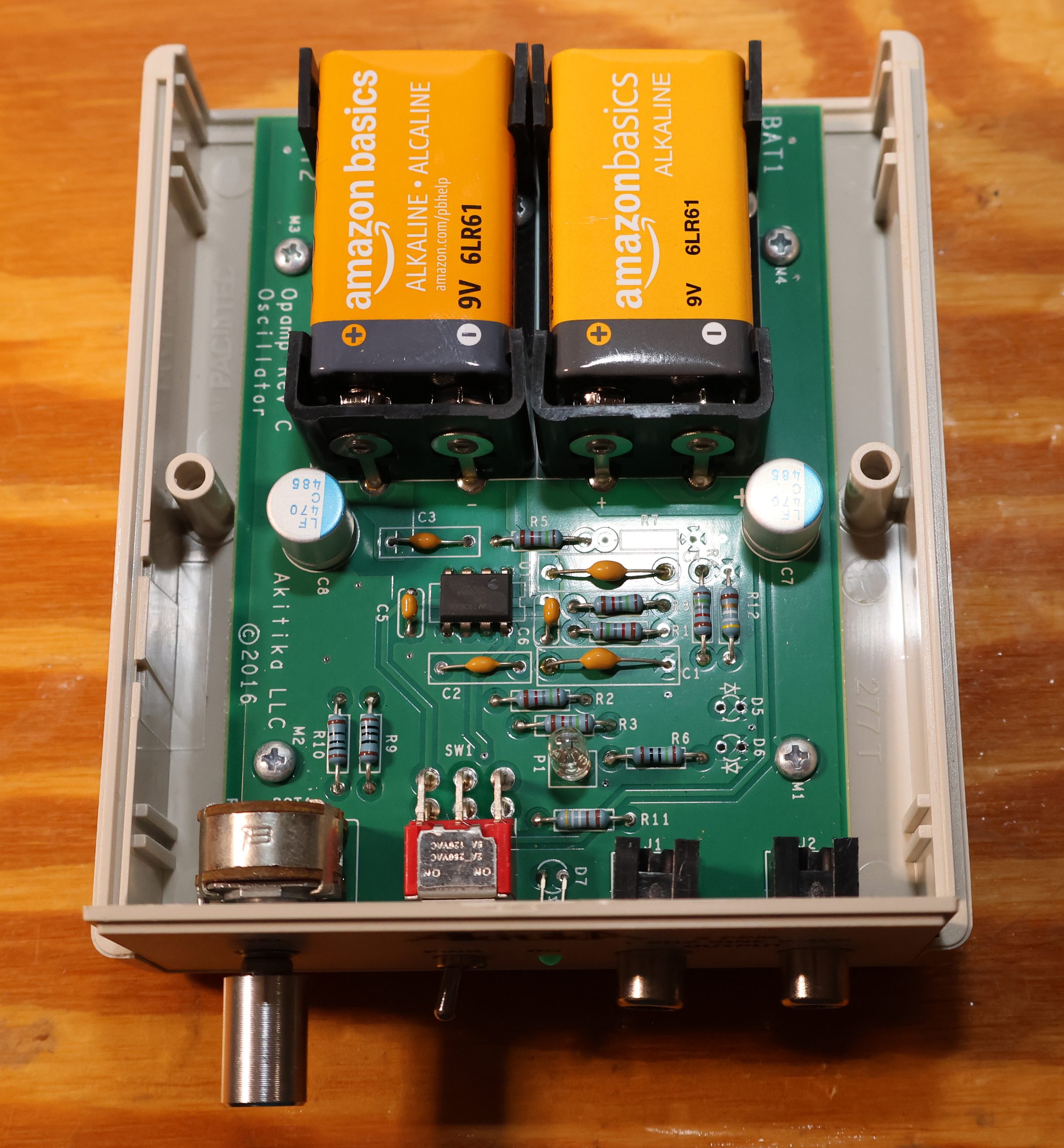
I bought the Akitika 2 PPM 1 kHz oscillator for one reason: I was tired of not knowing whether the distortion I was chasing lived in the amplifier on my bench or in the box feeding it. If you repair preamps and power amps you know the feeling: you hook up the bench function generator, run the FFT, see 0.02% sitting there, and spend the next hour wondering which half of that number is yours to fix. The Akitika ended that argument permanently, for less than the price of a decent set of test leads.
The topology is the whole trick. This is not the textbook Wien bridge everyone expects when they hear “lamp stabilized oscillator.” The loop is two cascaded active lowpass sections, each with a Q of roughly 4 to 5, tuned so their gain peaks at 1 kHz, one inverting and one not. Stack them and at 1 kHz the phase around the loop comes back to zero with gain slightly greater than one, which is the definition of an oscillator having a good day. Everywhere else, loop gain falls off a cliff. That is the elegant part: the same filtering that sets the frequency also attenuates the harmonics the amplifier stage generates on its way around the loop, so the circuit is continuously cleaning up after itself. A Wien bridge is a much shallower filter and leans harder on the amplitude control element to stay honest.
And the amplitude control is a light bulb. A tiny 1869D incandescent lamp, 14 mA, sitting in the feedback network exactly the way Bill Hewlett did it in 1939, because nobody has improved on it since. As output rises the filament heats, its resistance climbs, positive feedback drops, and the amplitude parks itself. What beats a JFET or diode limiter here is thermal inertia: a filament takes hundreds of milliseconds to change its mind, so it cannot correct within a single 1 millisecond cycle. It never modulates the sine wave, so it never manufactures harmonics. Every faster, cleverer, more modern amplitude control I have used does its correcting inside the cycle and dumps the evidence into the second and third harmonic, which is precisely where I am trying to look. Slow and dumb wins.
The specs, without getting tedious about it:
- Roughly 2 ppm distortion, 0.0002%, second harmonic about 115 to 118 dB down and third around 130 dB down
- 1 kHz within a percent or two, which is fine when you are measuring a device and not calibrating a frequency standard
- 1.5 V RMS maximum output, adjustable, on dual RCA jacks with a dual audio-taper level control
- Output impedance from 100 ohms wide open to about 2.5k at half rotation
- Two 9 V batteries, about 10 mA each, and a single LME49720 dual op amp doing all the work
- Around $89 as a kit, about an evening to build if you stop to eat
Battery power is not a cost-cutting compromise, it is a feature. There is no mains transformer, no safety earth, and no third wire arguing with the chassis of whatever I am repairing, so the generator floats completely. Anyone who has spent an afternoon chasing a hum that turned out to be their own test setup will understand why this matters more than any number on the spec sheet. There is also no 60 Hz or 120 Hz junk in the low end of my analyzer window, so when I do see supply garbage in the spectrum it belongs to the patient and not to me.
Here is why 2 ppm actually matters on a repair bench. Distortion measurement is a subtraction problem: whatever your source produces sets the floor, and you cannot see anything underneath it. A typical bench function generator sits between 0.1% and 0.5% THD, a thousand times worse than this. Feed that into a preamplifier and you are measuring your generator with a preamplifier attached. Feed the Akitika in and the residual on the screen belongs to the device under test, full stop. That one change makes real faults visible:
- Crossover distortion from a drifted or mis-set output stage bias, which lives almost entirely in the higher-order odd harmonics and hides completely under a dirty source
- A leaky or tired electrolytic in a feedback shunt path, which adds low-level nonlinearity long before it measures bad on a capacitance meter
- Oxidized relay contacts, dirty selector switches, and worn pot wipers, all nonlinear resistances that show up as a small forest of harmonics and vanish the instant you clean them
- An output device going soft, or a matched pair that is no longer matched, caught as second harmonic rising with level
- Channel comparison, since two jacks run off one dual gang control, so the good channel tells you what the bad one should look like
Setting bias is the job I use it for most. Run the amp into a dummy load at a few watts, notch out the fundamental, and adjust bias while watching the high-order hash collapse. With a source this clean the minimum is unmistakable, and you are setting bias by what the amplifier is actually doing rather than by a number in a service manual written when Carter was president.
Honest gripes, since it is not a lab instrument and does not pretend to be. One frequency, take it or leave it. The level control is a plain audio taper with no calibrated steps, so setting an exact input voltage means keeping a voltmeter in the loop. Output impedance climbs to a couple of kilohms as you back the level down, so I leave it near wide open and attenuate downstream. Give it a few seconds after switch-on for the lamp to settle before you trust the amplitude. And you will kill the batteries by leaving it on, which is why the LED exists and why I still manage to ignore it.
Final verdict: for anyone repairing preamplifiers and power amplifiers, this is the highest return per dollar of anything on my bench. It removes the single biggest source of uncertainty in distortion work, it does it with a circuit clever enough to be worth studying, and it does it for the price of a nice dinner. Build it, box it, keep spare 9 V batteries in the drawer, and stop wondering whether the problem is you.