
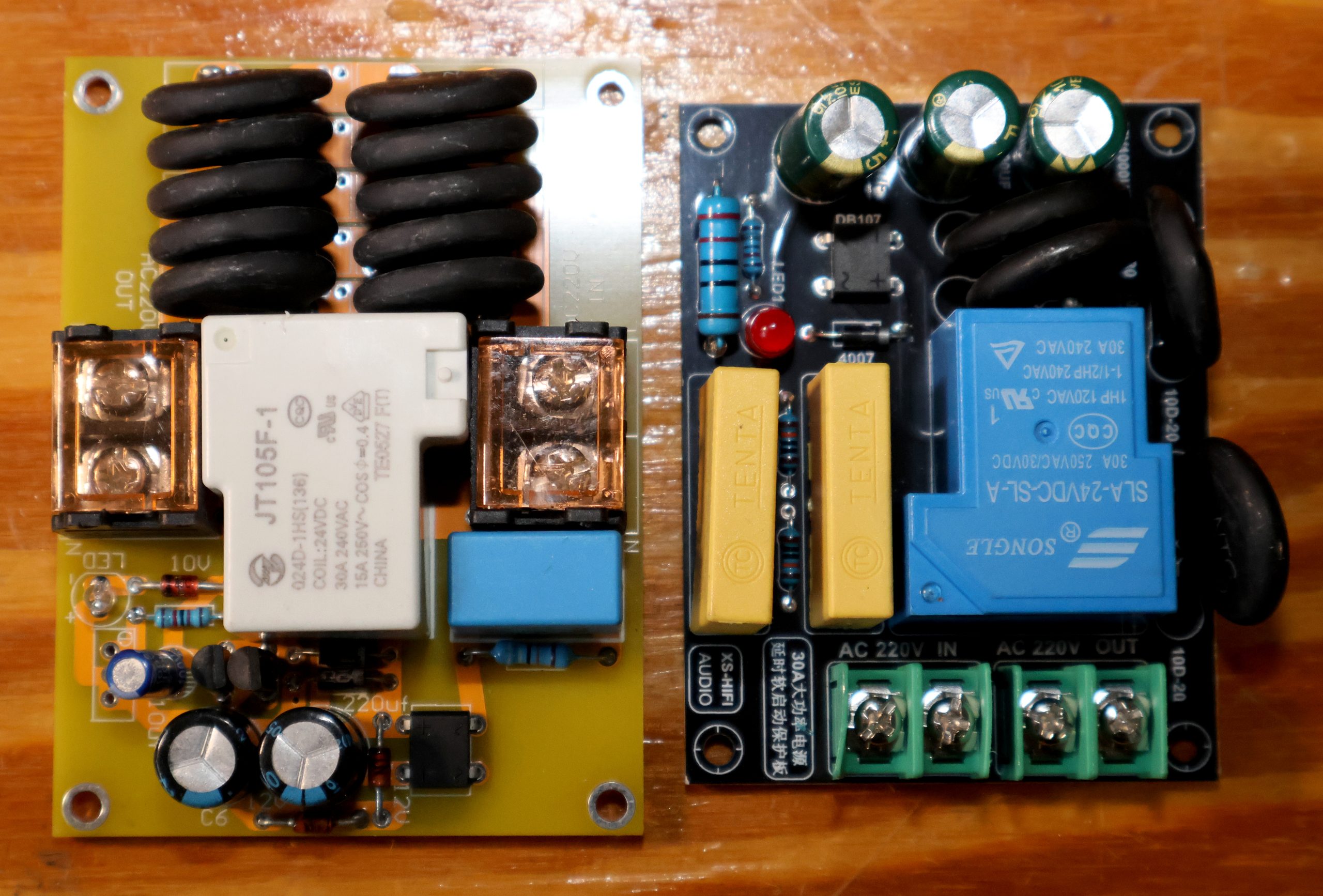
Two boards, the same job, two different philosophies
The photo shows a pair of AC mains soft-start / delayed-turn-on boards of the kind that sell for the price of a coffee and end up inside half the DIY power amplifiers on the planet. Both are labelled for 30A service, both switch 220–240V, both use a single relay. But look closer and they are engineered around completely different assumptions, and that shows up in how they behave in a real amplifier.
Why a powerful amplifier needs one in the first place
Switching on a big linear amplifier produces two surges that happen simultaneously, and neither has anything to do with the loudspeakers.
- Transformer magnetising inrush. When you break the mains, the core is left with residual flux. If you then reconnect at the worst moment in the cycle (near a voltage zero crossing) the flux demand adds to what is already stored, the core saturates, and for a few half-cycles the primary stops behaving like an inductor and behaves like its own copper resistance. On a 500–1000VA toroid that is roughly 0.5–3 ohms, so the peak current can reach 50–250A. Toroids are the worst offenders precisely because of what makes them attractive: no air gap, very high permeability, very low leakage inductance. There is nothing left to limit the current.
- Reservoir capacitor charging. A serious amplifier carries 20,000 to 100,000uF per rail pair, with milliohms of ESR. At the instant of switch-on those capacitors are discharged, which means the rectifier is looking into what is effectively a dead short. The first few charging pulses are limited only by transformer resistance and diode drop.
The consequences are familiar to anyone who has built a big amp: the household breaker trips (a 10A type B breaker will magnetically trip somewhere around 30–50A, and it does not care that the surge only lasts 10 milliseconds), the mains switch contacts weld or erode, fuses fatigue and eventually blow for no visible reason, the transformer emits a mechanical thump as the windings jump, and the lights in the room dip. Repeated over a few thousand switch-on cycles, the damage is cumulative: pitted switch contacts, cracked rectifier dies, capacitors that have been abused with current pulses far beyond their ripple rating.
A soft-start board fixes all of this with a very old idea: put something resistive in series with the mains for the first second or so, then short it out once the transient is over.
What both boards have in common
Both are wired in series with the transformer primary, between the mains switch and the transformer. Both use the same three-block architecture:
- A current limiting element in the live line — here, banks of black disc NTC thermistors.
- A relay whose contacts sit directly across that limiting element, so that closing the relay shorts it out and removes it from the circuit.
- A timer that decides when the relay closes, powered directly off the mains through a transformerless capacitive dropper.
An NTC thermistor is a very neat choice for the limiting element. Cold, a 10D-20 is about 10 ohms; as the surge heats it, its resistance collapses to well under an ohm within a second or two. So it is a resistor that gets out of the way by itself, and the relay only has to finish the job.
The capacitive dropper is worth understanding because it explains the rest of the board. A film capacitor across the mains has a reactance of 1/(2·pi·f·C) — about 6.8k for 0.47uF at 60Hz — and behaves as a crude constant current source of a few tens of milliamps. That current is rectified, smoothed, and used to pull in a 24V relay coil. It is cheap, tiny, and produces no heat. It also means the entire low-voltage section of these boards floats at mains potential. There is no isolation anywhere on either PCB.
The left board: brute force in the limiter
The yellow board puts almost all of its silicon-free budget into thermal mass. There are two banks of five large NTC discs, ten in total, arranged as series-parallel groups and laid on their sides with air gaps between them so they can shed heat.
The switching element is a JT105F-1 sealed power relay, 24V coil, rated 30A at 240VAC resistive — note the second line on the case, 15A at 250VAC with cosine phi = 0.4, which is the honest inductive rating and the one that actually applies to a transformer. Input and output land on covered barrier terminal blocks, which is the right connector class for tens of amps.
The timing section is modest: a mains film capacitor as the dropper, a small bridge rectifier, a zener clamp and two electrolytics of roughly 220uF and 100uF. That is a few hundred microfarads of reservoir, which gives a comparatively short delay — expect a fraction of a second to around a second rather than a leisurely pause.
One caution: the silkscreen on this board (a “10V” marking next to what appears to be a zener, while the fitted relay has a 24V coil) does not obviously match the populated parts. These PCBs get re-used across variants, so trust the components, not the printing.
The right board: fewer thermistors, a longer timer
The black XS-HiFi board, marked as a 30A high-power delayed soft-start protection board, spends its budget differently. It carries a smaller NTC bank — the silkscreen calls for 10D-20 parts — and instead invests in the timing circuit: a DB107 bridge, a pair of yellow film capacitors as the dropper, a series resistor, a 1N4007 flyback diode across the coil, and three substantial 1000uF electrolytics.
Those three capacitors are the interesting part, because they are not there for smoothing. Fed from a roughly constant-current dropper, a capacitor charges as a straight ramp: dV/dt = I/C. Three thousand microfarads charged at, say, 40mA takes on the order of one and a half to two seconds to reach the pull-in voltage of the SLA-24VDC-SL-A relay. The reservoir is the timer. That is an elegant way to get a long, repeatable delay with no IC, no 555, no microcontroller.
The relay is the ubiquitous Songle SLA, rated 30A at 250VAC, 1HP at 120VAC. It is a competent part but its ratings are optimistic, and its contacts are noticeably less substantial than the JT105F’s. The bigger compromise is at the edge of the board: the green pluggable screw terminals. That style of connector is typically good for 10–16A depending on the exact family. On a board advertised at 30A, that is the weakest link in the whole chain.
So why two different topologies?
Because there are two ways to survive the same energy pulse, and each board picked one.
The energy dumped into the limiter during startup is roughly fixed by the load: it is the energy needed to charge the reservoir bank, about half C times V squared, plus the transformer’s magnetising losses. You cannot avoid it. You can only choose where it goes.
- Spread it over more mass. Ten thermistors share the joules, each one runs cooler, the bank’s cold resistance is lower (so the amplifier gets closer to full voltage during the ramp), and — critically — the bank cools back down faster between power cycles. That is the yellow board. It can afford a shorter delay because its limiter never gets close to its energy rating.
- Spread it over more time and less mass. Fewer thermistors, but a delay long enough that the charging transient is comprehensively over before the relay slams shut. That is the black board. Its long timer is not a luxury, it is a requirement: with a smaller limiter you have less margin, and closing the relay early produces a second inrush surge into a still-partly-charged capacitor bank, which defeats the whole exercise.
There is also a plain commercial reason. The black board is smaller, cheaper to populate, and uses standard 20mm discs and generic terminals. The yellow board costs more in copper, connectors and thermistors, and is aimed at people who already know their toroid is 800VA.
The hot-thermistor problem nobody mentions
NTC limiting has one genuine weakness, and both boards share it. A hot thermistor is a low-value resistor. If the mains blinks for 200ms, or you switch the amp off and immediately back on, the NTCs have not cooled and provide almost no limiting on the next switch-on. You get the full unrestrained inrush.
The bigger bank on the yellow board recovers faster in absolute terms simply because each disc ran cooler, but neither board solves the problem properly. The topology that does is a wirewound power resistor plus relay: a resistor does not care how hot it is, its value is essentially the same on the second switch-on as on the first. That is why serious commercial amplifiers, and the more expensive DIY boards, use resistors rather than thermistors. It is the third topology in this family, and it is worth knowing that it exists.
Which board is better?
For a genuinely powerful amplifier — a 500VA or larger toroid, 40,000uF or more of reservoir capacitance, or a mains circuit protected by a fussy type B breaker — the left (yellow) board is clearly the stronger design. The reasons are unglamorous but decisive: five times the thermistor mass, a busbar instead of a PCB trace for the high-current path, barrier terminals that can actually take 4mm cable and 30A, a better-specified relay, and a contact snubber. The one thing to verify before you trust it is the delay time, because its small timing reservoir suggests a short one. Power it up on the bench with the amp connected and confirm the relay clicks after the reservoir capacitors are essentially charged, not during. If it closes too early, adding capacitance across the timing electrolytic is a one-component fix.
The right (black) board is the better value for a moderate amplifier — say up to 300–500VA and 20,000uF — where its longer, well-behaved delay is genuinely useful and its smaller thermistor bank is never stressed. It is also the more sensibly laid-out board electrically. But do not believe the 30A number: the terminals will not honour it, and if you intend to run anything near that, you should be landing the mains on proper barrier strips instead.
What I would change on either one
- Add a fuse ahead of the board. Neither has one, and a shorted thermistor or a welded relay is a fire, not an inconvenience.
- Add a MOV (a 275V class device) across the incoming line. These boards do nothing about surges, only about inrush.
- Check the relay contact rating against the inductive figure, not the resistive headline number. A transformer primary is an inductive load.
- Both switch only the live line. Neutral passes straight through, so the board is not an isolator and must never be treated as a mains switch.
- Mount either board on standoffs with real clearance, and remember that every part of the low-voltage section is live because of the transformerless supply. That includes the LED and the relay coil. Do not probe it with a grounded oscilloscope, and do not let it touch the chassis.
Both boards do the fundamental job, and either one is a large improvement over connecting a 1kVA toroid straight to the wall. The difference between them is margin — and margin is exactly what you are buying when the thing on the other end of the wire is a 500 watt amplifier.