
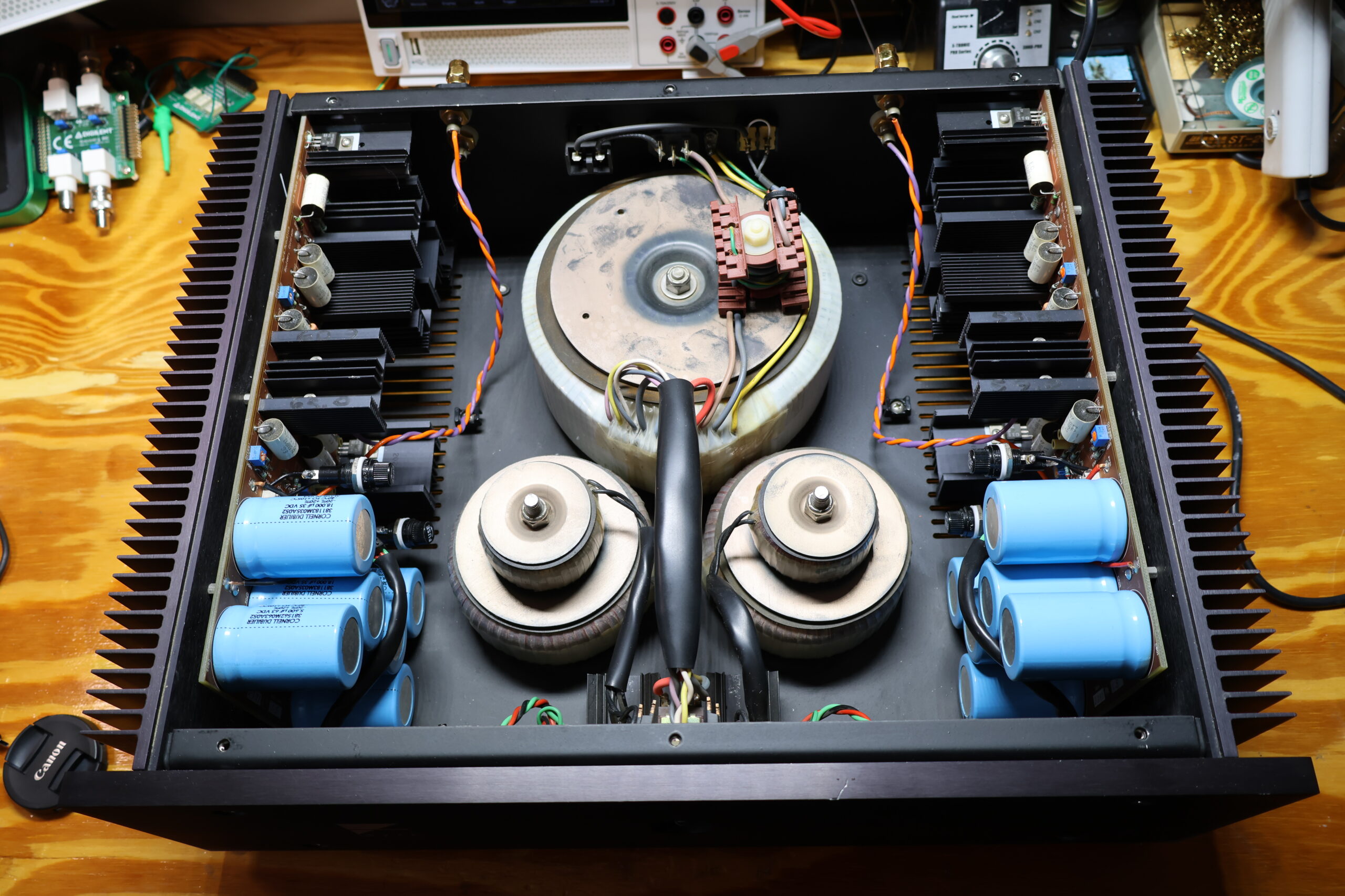
There is a distinct satisfaction that comes with working on a piece of high-end audio equipment designed with real engineering discipline. The Ayre V-3 power amplifier is a classic example. When a customer brought this unit into the shop, the aesthetic appeal of the enclosure was immediately clear, but the complaint was a familiar headache for any audiophile: one channel would intermittently fade out during listening sessions.
Intermittent audio drops can point to a wide variety of gremlins, ranging from failing semiconductor junctions to dirty relay contacts or thermal breakdown in power components. Fortunately, when a channel fades rather than going into a hard, latching protection fault or blowing a primary rail fuse, it is rarely caused by a failure in the main output transistors. For an owner of an Ayre V-3, that is exceptionally good news—the output devices used in this topology are virtually impossible to source on the modern replacement market today, making their preservation a top priority during any service session.
Inside the Chassis: Design and Architecture
Opening up the Ayre V-3 reveals an internal layout that reflects high-grade design and deliberate manufacturing:
- Modular Access: Each amplifier channel board is positioned for straightforward access. Technicians do not need to disassemble half the chassis just to probe key test points or access the solder side of the PCBs.
- Component Placement: Critical heat-generating components are isolated. The main power supply filter capacitors are physically separated from the hottest sections of the heatsinks and driver stages, shielding them from ambient thermal stress.
- Filter Capacitors: The primary electrolytic filter capacitors are high-spec components. When pulled for out-of-circuit testing, they measured with low Equivalent Series Resistance (ESR) and full rated capacitance, performing like new despite their age.
- Signal Path Capacitance: Aside from the primary power reservoir, the rest of the circuit relies almost entirely on high-grade film capacitors. Unlike electrolytic capacitors that dry out and drift in value over time, film capacitors do not suffer from chemical degradation and will effectively last indefinitely under normal operating parameters.
Diagnosing and Resolving the Fault
Because the output devices and main power supply rails were functioning within spec, the investigation turned to the small-signal input stage to trace the cause of the dropping channel.
- Input Signal Tracing: Signal tracing along the balanced input path revealed a intermittent drop right where the differential signal enters the board.
- Visual & Mechanical Inspection: Under magnification, the issue was identified at the solder connections for the XLR input connector. Years of plugging and unplugging heavy interconnect cables, combined with thermal cycling, had created micro-fractures in the solder joints securing the XLR pin headers to the board.
- Reflowing & Joint Refresh: The existing, oxidized solder was removed from the affected input pins, and the joints were reflowed with fresh, high-silver-content solder.
- Preventative Touches: To prevent future cold-solder failures, all surrounding mechanical and signal points across both input boards that showed signs of stress or dullness were systematically reflowed.
Calibrating DC Offset and Bias
With the signal path restored and continuous output established on both channels, the final phase of servicing involved verifying the amplifier’s operating points to ensure peak performance and thermal stability.
+-------------------------------------------------------------------------+
|                         REPAIR & TUNING CHECKLIST                       |
+-------------------------------------------------------------------------+
| [X] Verify Primary Power Supply ESR & Capacitance                      |
| [X] Inspect Film Capacitors & Signal Path Integrity                      |
| [X] Desolder & Reflow Fractured XLR Input Pins                           |
| [X] Reflow Thermal-Stressed Auxiliary Board Connections                  |
| [X] Calibrate DC Offset                                                 |
| [X] Set Output Stage Bias Voltage                                       |
| [X] Extended Thermal & Load Stress Test                                  |
+-------------------------------------------------------------------------+
DC Offset Adjustment
DC offset was measured across the 2 capacitors with no input signal applied. Adjusting the offset trimpots (there are 4 per channel!) I got as close as possible to the Ayre’s recommended values.
Output Stage Bias Alignment
The bias current was recalibrated to factory specifications (1400 mA). Setting the correct bias ensures the output devices operate smoothly in their optimal class-A bias window.
Conclusion and Listening Test
After a full day on the test bench undergoing thermal soak testing under load, the Ayre V-3 performed flawlessly. The intermittent channel drop was entirely gone, the soundstage was perfectly balanced, and the noise floor remained dead silent.
Servicing equipment like the V-3 is a reminder of the value of high-quality audio engineering. Because the original design prioritized proper thermal management and top-tier passive components, a simple repair of a stressed input connection and a quick bias recalibration brought this classic amplifier back to its original performance standards. It is ready to deliver clean, effortless power for many more years to come.