
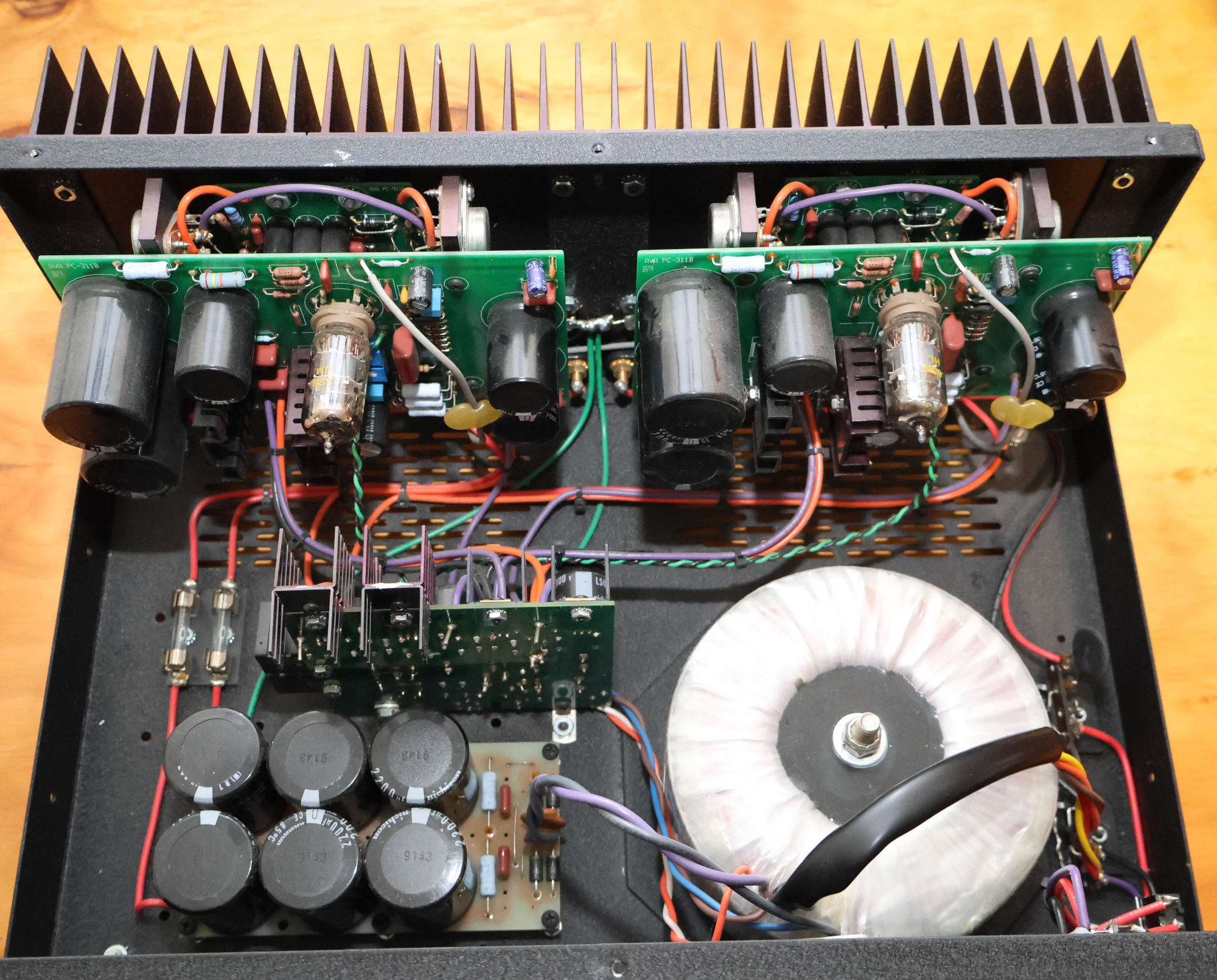
The Audio by Van Alstine (AVA) FET Valve 400R remains a standout piece of high-end audio engineering. Combining the sweet, liquid midrange of a vacuum tube front-end with the effortless drive, stability, and speed of a MOSFET output stage, it delivers a musical presentation that rivals modern amplifiers costing far more.
If you own or are restoring a FET Valve 400R, servicing it is well worth the time. Proper maintenance—specifically setting the DC balance and output bias—ensures optimal performance, long-term stability, and cool operation.
Safety & Setup Prerequisites
- Safety First: Unplug the amplifier from the AC wall outlet before opening the chassis or moving test leads. High voltages are present inside.
- Warm-up: Allow the amplifier to idle for 15–20 minutes before making final adjustments so internal temperatures stabilize.
- Meters Required: You will need a Digital Multimeter (DMM) set to measure DC Volts and a DC Ammeter (or DMM set to DC Current).
- Meter Protection: Ensure your ammeter can handle high current surges (5–10 A minimum during turn-on) to prevent blowing the fuse inside your meter.
1. Adjusting the DC Balance
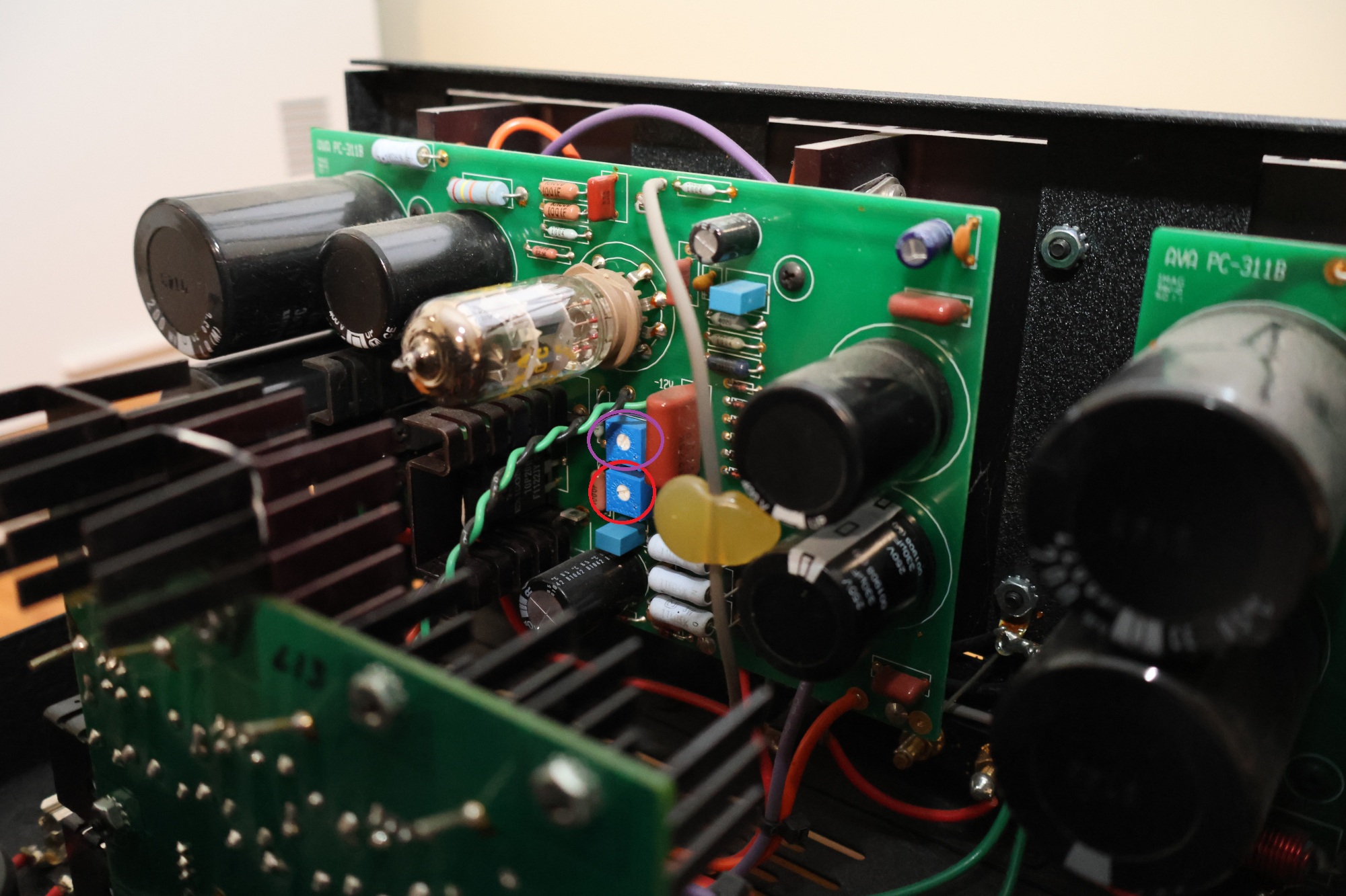
The 250k trim pot controls the DC balance of the circuit (top trim pot circled in Purple). This adjustment ensures the amplifier clips symmetrically (top and bottom) when driven past its maximum power output.
- Target Measurement: Set the DC voltage on the source (metal case) of the output MOSFETs to half of the regulated power supply voltage.
- Procedure:
- Measure the DC voltage on the source (metal case) of the regulator MOSFETs to establish your main regulated supply voltage (top Mosfet).
- Measure the DC output voltage before the large output coupling capacitors at the source (metal case) of the output MOSFETs (2 bottom Mosfets).
- Adjust the 250k trim pot until the voltage at the output MOSFET source equals exactly 50% of the regulated supply voltage measured in Step 1.
2. Setting the Bias (Idle Current)
The 100 Ohms trim pot controls the bias, establishing the idle current running through the output stage when no signal is present.
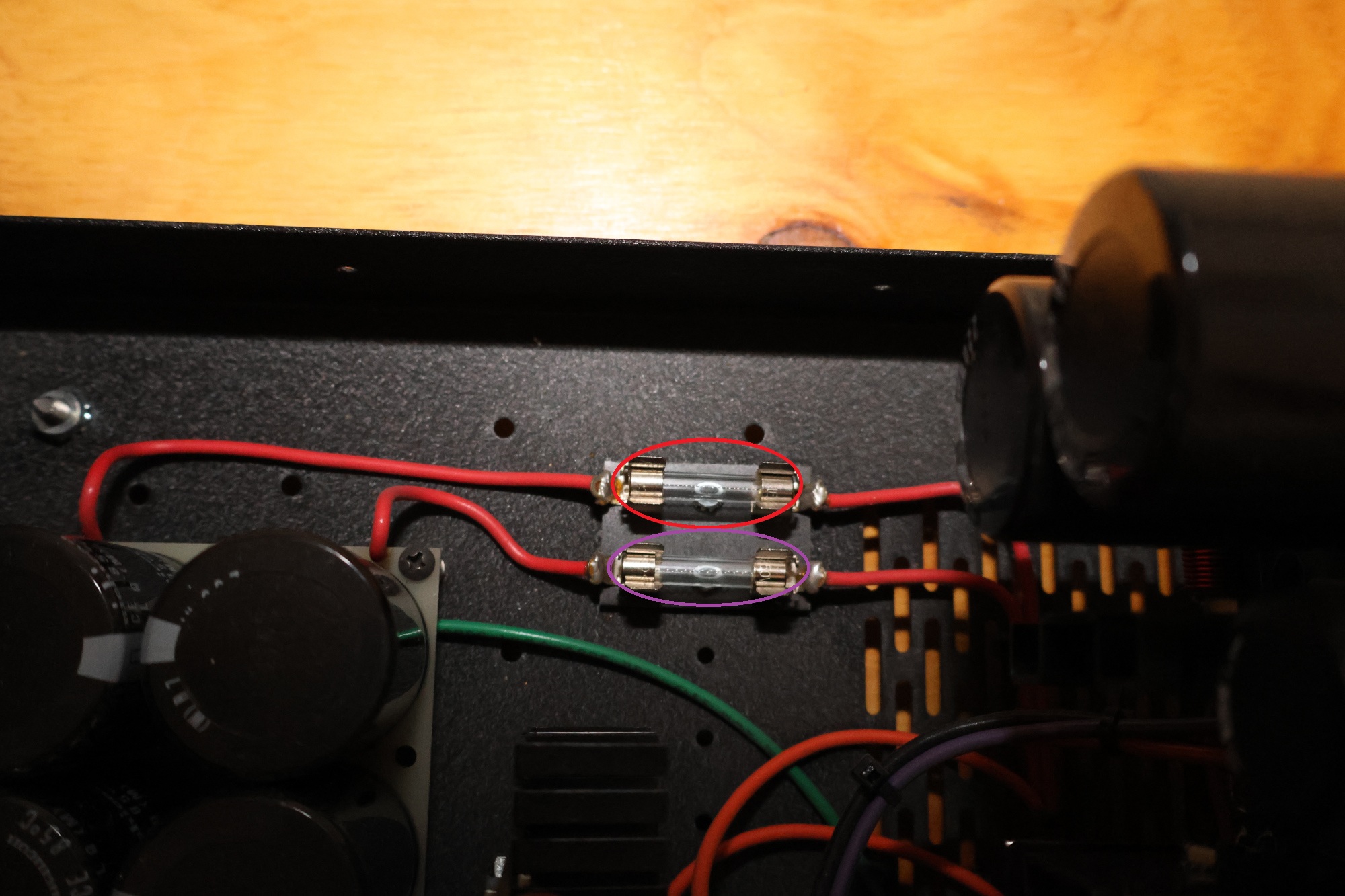
- Measurement Setup: Remove the main internal DC fuse (do not remove the main AC line fuse) and connect your DC ammeter across the fuse holder terminals. There are 2 fuses, remove one at a time and bias that channel.
- Factory Specs vs. Modern Practice:
- Original Spec: 65 mA per MOSFET device (130 mA total for the 400R). At that setting, the amp will be heavily class A biased, but will also run hot 115-125 F
- Recommended Target: 40 mA to $50 mA total. Amp still sounds great, but runs much cooler.
- Procedure:
- Ensure no audio input signal is playing (inputs grounded or volume muted).
- Power on the amp with the ammeter in place of the internal DC fuse.
- Adjust the 100 Ohms trim pot until your ammeter reads between 40 and 50 mA.
Note: All crossover distortion in the FET Valve circuit disappears at approximately 25 mA. Setting the bias to 40-50 mA keeps the amplifier well clear of crossover distortion while allowing it to run significantly cooler and quieter than the original 130 mA specification, without any loss in sound quality.
Once both channels are balanced and biased, allow the unit to run for another 10 minutes, double-check your readings, re-install the internal DC fuse, and replace the top cover. Re-biasing your FET Valve 400R ensures this classic design continues to sound its best for years to come.