
A practical guide to setting quiescent current on a Burmester 909 clone — and why its DC offset is not your problem.
The Transaudio T9.4 is one of the better-executed Chinese takes on the Burmester 909: a 36 kg, dual-mono, 225 W/8 Ω (450 W/4 Ω) class AB stereo amplifier that shows up in various guises — Transaudio T9.4, ASYPDZSW BL9, and a handful of unbranded “Reference X-Amp” boards from the same board house. They all share a circuit, and they all share the same two questions from new owners: what’s my DC offset supposed to be, and how do I set the bias.
Short answers: don’t chase the offset, and set the bias to 56 mV across each 0.47 Ω emitter resistor. The long answers are more interesting.
The topology, briefly
The T9.4 implements Burmester’s X-Amp arrangement: a fully complementary, fully symmetrical amplifier that is balanced from the input pins all the way to the speaker terminals, and DC-coupled throughout — no coupling capacitors anywhere in the signal path.
“Fully symmetrical” here has a specific meaning, and it’s not marketing. Where a conventional amplifier has one differential input pair feeding one voltage-amplification stage (VAS), the X-Amp has two of everything, mirrored: an NPN input pair and a PNP input pair, each driving its own VAS, the two halves meeting at the output stage. The top half handles the positive-going signal, the bottom half the negative-going, and each is the other’s mirror image.
Three consequences fall out of that, and they matter for everything below:
- Even-order distortion products cancel between the halves rather than being corrected by feedback after the fact.
- Slew rate is symmetrical — the amp doesn’t have a “fast edge” and a “slow edge,” which is a common asymmetry in single-ended-VAS designs.
- DC drift is largely common-mode. When the two halves warm up, they drift together, and the difference — which is what appears at the speaker terminals — is far smaller than either half’s individual drift. Hold onto this one.
The output stage is seven pairs of Sanken bipolars per channel, matched, on a big extruded heatsink, in an emitter-follower configuration with individual 0.47 Ω emitter degeneration resistors. Power comes from two 800 VA transformers, one per channel, each feeding its own bank of eight 10,000 µF reservoir caps — 160,000 µF in the box.
Rails land somewhere in the ±63 V to ±70 V region. Measure yours; the number matters for the sanity check later.
DC offset: why there’s nothing to adjust
Every DC-coupled amplifier has the same structural hazard. There is no capacitor between the output stage and your woofer, so any DC that appears at the output goes straight into a voice coil that has maybe 4 Ω of resistance and no way to dissipate the heat. A sustained 1 V of offset into a 4 Ω driver is a quarter-amp of DC through the coil, forever.
Designers solve this one of two ways: trim it out by hand and hope it stays trimmed, or build a servo. The T9.4 builds a servo.
What’s actually on the board
There’s an OP07 precision op-amp on each channel’s board wired as a DC servo. The OP07 is a deliberate, slightly old-fashioned choice and a correct one: it’s a bipolar-input part specified for very low input offset voltage and, more importantly, very low offset drift over temperature. It has essentially no audio-bandwidth job to do, so its unremarkable speed doesn’t matter. What matters is that its own DC error is small enough not to become the thing it’s supposed to be correcting.
How a DC servo works
The servo is an integrator in a feedback loop around the amplifier’s DC behavior:
- It watches the amplifier’s output and compares it to ground.
- It integrates that error over a long time constant — the corner frequency sits well below the audio band, typically a fraction of a hertz.
- Its output injects a small correction current or voltage into the input stage, nudging the amplifier’s operating point until the output error integrates to zero.
The long time constant is the whole trick. To a 20 Hz bass note, the servo is invisible — it simply cannot respond that fast, so it applies no correction to music and adds nothing to the signal path. To a slow thermal drift over thirty minutes of warm-up, the servo has enormous loop gain and crushes the error to near nothing.
Why you can stop worrying
Put the two facts together — a symmetrical topology whose drift is mostly common-mode, wrapped in an integrator with huge DC loop gain — and offset is a solved problem in this amplifier, by design, and there is no offset trimpot for you to turn. There is nothing to adjust because nothing needs adjusting.
What you should do instead is verify, once:
- Speakers disconnected, inputs shorted or terminated, amp warmed up.
- DMM on DC millivolts across the speaker terminals.
- Expect single-digit to low-double-digit millivolts. A few mV is typical. Under 20 mV is fine. Under 50 mV is still unremarkable for a big class AB amp.
- Expect it to wander a little. You will watch the reading drift a few mV up and down and settle. That is the servo doing its job in real time, not a fault. A rock-steady reading in a servo’d amp is actually the less informative result.
Two things that are faults, and are worth knowing so you can tell them apart from normal behavior:
- Hundreds of millivolts, or a reading that climbs and doesn’t come back. That’s not servo behavior. That’s an unpowered or disconnected servo, a jumper left off, or a failed device — and the servo cannot fix a broken output stage. It can only correct errors small enough to be inside its correction range.
- Offset that changes when you touch the bias trimmer. It shouldn’t, materially. Bias and offset are independent adjustments in this topology, and if yours are coupled, something is wrong upstream. Never, ever try to null offset by moving the bias pot.
There is also a speaker protection relay board with DC detection sitting between the output stage and the binding posts, as a backstop. It is not a substitute for the servo — it’s the thing that saves your drivers on the day a Sanken shorts.
Biasing: what you’re actually setting
Bias — quiescent current, idle current, Iq — is the current flowing from the positive rail, through the NPN output devices, through the PNP output devices, to the negative rail, when there is no signal. It does no work. It exists to keep both halves of the output stage conducting through the zero crossing.
With zero bias, each device shuts off completely for half the waveform, and the handoff between halves happens in the region where both are in the sluggish, nonlinear part of their transfer curve. That’s crossover distortion: a small notch at the zero crossing, present at every signal level, which means it’s a larger percentage of the signal at low levels than at high ones. It’s the distortion mechanism that makes an amplifier sound hard and grainy on quiet passages, and it’s the one that global feedback is worst at cleaning up, because it’s a high-order, wideband artifact.
Bias fixes it by keeping both halves alive across the handoff. Too little and you get the notch. Too much and you waste power, run hot, and shorten device life — with no distortion benefit past a certain point.
The textbook number, and the T9.4’s number
For an emitter-follower output stage, the classic result (Oliver’s condition) is that distortion is minimized when the quiescent voltage across each emitter resistor is roughly 26 mV — a number that falls out of the thermal voltage kT/q, not out of the specific transistors. With 0.47 Ω emitter resistors, that’s:
26 mV / 0.47 Ω = 55 mA per device
The T9.4 is specified at 120 mA per transistor — more than double the textbook optimum. That’s deliberate, and it’s inherited from the Burmester design philosophy. The reason isn’t further crossover-distortion reduction; you’ve already had that. It’s that a heavily over-biased class AB output stage operates in pure class A up to a meaningful output level, and only transitions to AB above it.
Here’s the window on this amp:
- 7 pairs × 120 mA = 840 mA total idle current per channel
- The stage stays in class A up to a peak load current of 2 × 840 mA = 1.68 A
- Into 8 Ω, that’s 13.4 V peak → about 11 W in class A
- Into 4 Ω, that’s 6.7 V peak → about 5.6 W in class A
Eleven watts covers a great deal of ordinary listening on efficient speakers. The design intent is that the amplifier is running class A for most of what you actually hear, and only calls on the AB region for peaks.
Targets
Set 56 mV DC across each 0.47 Ω emitter resistor.
| What you measure | Target | Corresponding current |
|---|---|---|
| Across one 0.47 Ω emitter resistor | 56 mV | 120 mA per device |
| Across both resistors of one pair (in series) | 113 mV | 120 mA through the pair |
| Total per channel (all 7 pairs) | — | 840 mA |
Practical acceptance window, per device:
| Reading | Current | Verdict |
|---|---|---|
| Below 26 mV | < 55 mA | Under the textbook optimum. Crossover distortion is rising. Fix it. |
| 26–40 mV | 55–85 mA | Safe, clean, cooler than spec. A legitimate choice if your amp lives in a warm room or a cabinet — you keep essentially all of the crossover-distortion benefit and give up most of the class A window. |
| 50–56 mV | 105–120 mA | Factory intent. Set here. |
| Above 60 mV | > 128 mA | Too hot. No benefit. Back it off. |
A note on spread: you have one trimmer setting fourteen devices. Emitter resistors carry a tolerance, Vbe’s differ even among matched devices, and the heatsink has a thermal gradient across it. Expect ±10–15% device-to-device. Aim for the average across the channel to hit target, and make sure no single device sits far above the rest — one device reading 75 mV while its neighbors read 50 mV is a matched-set problem or a bad solder joint, not something to trim around.
The procedure
Before you open it
This amplifier will hurt you if you are careless. Rails around ±65 V, referenced to each other, means about 130 V across the output stage — well into lethal territory. And there is 160,000 µF of storage in there, which does not discharge the instant you pull the plug.
- Unplug and wait several minutes before touching anything. Verify the rails have discharged with your meter before working near them, not after.
- Work one-handed. Keep the other hand in your pocket or behind your back. This is not folklore; it keeps current from crossing your chest.
- Use insulated probes with fine tips. The single most common way people destroy an amplifier during biasing is a probe slipping across two adjacent points and shorting a rail into the output stage. You will kill a row of Sankens in microseconds and probably the drivers with them. Probe clips beat handheld probes here.
- Speakers disconnected. Bias is set into no load.
- Inputs shorted or terminated, nothing playing.
Setting it
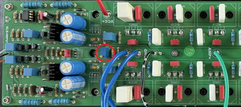
- Locate the bias trimmer. One per channel, on the driver board, near the output stage (highlighted with Red circle on the image).
- Pick a reference device. Choose one output transistor near the middle of the heatsink and clip your meter across its emitter resistor. Middle of the sink, not the end — you want a device at a representative temperature.
- Note the starting value before you touch anything. Write it down. If the adjustment goes sideways, you want to be able to get back.
- Turn the trimmer fully counter-clockwise first — to minimum bias — then bring it up. Never start by turning an unknown trimmer up. If it’s the wrong pot, or the wiper is dirty, you want to find out at low current.
- Bring it up slowly, in small steps, pausing between them. Bias responds to a trimmer immediately but then keeps moving as the heatsink temperature follows. Turn a little, wait, read.
- Set cold, then let it settle. Aim for roughly 45–50 mV cold. As the amplifier warms, the reading will climb toward target. Setting a cold amp to 56 mV puts you well over spec an hour later.
- Warm up properly and re-check. Lid on, no signal, 30–45 minutes. Then re-check at 10, 20, 30, and 60 minutes. You are looking for the reading to rise and then stabilize. If it rises and keeps rising — that is thermal runaway, and you shut down immediately and go look at the Vbe multiplier’s mounting.
- Trim to final target warm. With the amp at thermal equilibrium, adjust to 56 mV. Lid on for the last check if you can manage it; an open case runs cooler than the real operating condition and will read low.
- Survey the whole channel. Now walk your meter across all seven pairs and record every reading. This takes five minutes and tells you more about the health of the output stage than any single measurement.
- Repeat for the second channel. It’s dual mono — two independent adjustments, and there is no reason to expect the same trimmer position on both.
- Re-check DC offset at the speaker terminals when you’re done. Not because biasing should have changed it, but because you want the confirmation that it didn’t.
- Write it all down — the date, ambient temperature, the fourteen readings, the offset on both channels. In two years when you’re wondering whether something has changed, this page is the only way you’ll know.
Sanity-checking the numbers
Do this arithmetic on your own amp, because it’s the check that catches a mis-set bias when everything else looks fine.
At 840 mA per channel with ±65 V rails, the output stage alone dissipates about 109 W per channel at idle — 218 W for the pair, before the front end and transformer losses. Per device that’s about 7.8 W, which is comfortable for MT-200 Sankens with a heatsink of this size.
But 218 W is a real space heater, and it’s noticeably more than the ~180 W idle figure that gets quoted for this amplifier. Trust your own measurements over the published number. Put a power meter on the wall socket. If your amp idles well under 200 W, it is biased below the 120 mA/device spec — which is not a fault, and may well be how it left the factory. Decide where you want it, set it there deliberately, and record it.
The heatsinks should be warm to hot but touchable — you should be able to keep a hand on them. If you can’t hold a hand on the sink at idle in a normal room, you’re over-biased regardless of what the meter says.
Stay safe and have fun!