
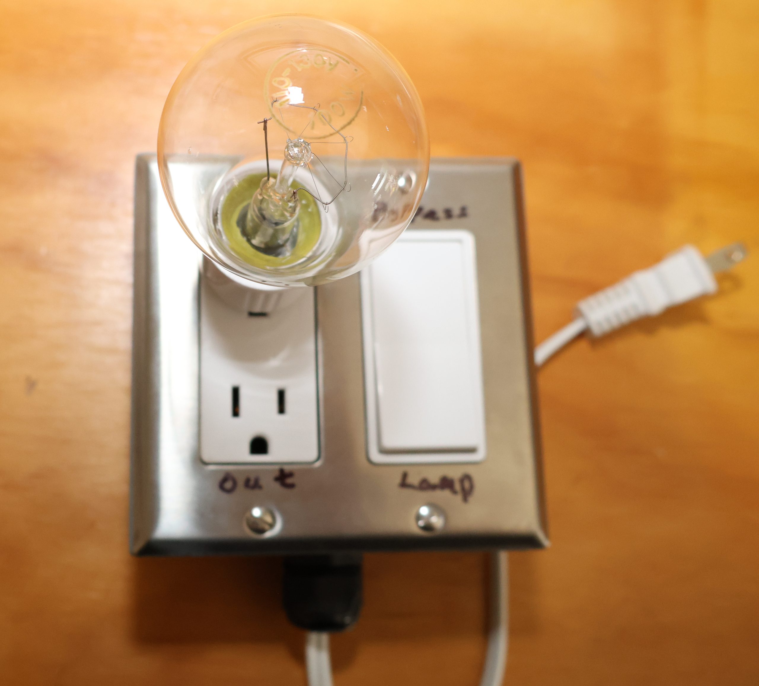
The usual first fault in mains-powered electronics is a dead short across the line — a shorted rectifier diode, a blown switching MOSFET, a punched-through mains filter capacitor, a shorted output transistor. Plug that straight into the wall and the only thing standing between the board and a 15 A branch circuit is the device’s own fuse. In the milliseconds before that fuse opens, tens of amps flow. That surge is what turns a one-part failure into a scorched trace, a cracked transformer, a vaporized bond wire in the part you just replaced, and a repair that is no longer worth doing.
What the bulb does. An incandescent filament is a self-adjusting series resistance. Cold it measures only ten to twenty ohms; as current heats it, its resistance climbs roughly tenfold. Wired in series with the device, it behaves like a soft current source:
- Normal load — the filament stays cool and near its low resistance, so it drops very little voltage and the device runs more or less normally.
- Shorted load — the filament goes fully incandescent and clamps the current at the bulb’s rated current, with nearly the whole 120 V dropped across the bulb instead of the fault.
| Bulb | Hot resistance | Current a dead short is clamped to |
|---|---|---|
| 40 W | ~360 Ω | ~0.33 A |
| 60 W | ~240 Ω | ~0.50 A |
| 100 W | ~144 Ω | ~0.83 A |
| 150 W | ~96 Ω | ~1.25 A |
A fraction of an amp cannot damage anything. The fault becomes something you can sit and study instead of something that destroys evidence in the first half-cycle.
What you get out of it.
- Non-destructive first power-up on unknown, water-damaged, recapped, or freshly repaired gear.
- Instant diagnosis with no instruments. The bulb is an ammeter you can read across the room: bright and steady means short, flash-then-dim means healthy inrush, dim glow means normal operation.
- Protection for the part you just installed. If the root cause is still present, the replacement survives to be re-used rather than dying with the first switch-on.
- Gentle capacitor reforming in vintage equipment — electrolytics that have sat for decades can come up slowly instead of venting.
- No blown fuses. You can power up, observe, shut down, and try again a dozen times without consuming anything.
- Cheap and passive. A socket, a bulb, and a switch, with nothing in it that can itself fail dangerously.
Why the bypass switch. Not every fault shows up at reduced voltage. Switching regulators may refuse to start, relays may not pull in, and thermal or intermittent faults can hide until the device is running for real. The bypass lets you clear the limiter out of the circuit and go to full line voltage without unplugging and re-cabling — once the lamp test says it is safe to do so.
What it does not do.
- It does not isolate you from the mains. Both legs at the “Out” receptacle are still line-referenced — that is the isolation transformer’s job.
- It will not catch high-impedance faults, which draw too little current to light the bulb.
- The voltage drop means the device is not operating under true conditions; final testing still has to happen at full voltage.
- It is not a variac. There is no adjustment beyond swapping bulbs.

Operation
- Start with SW1 in the LAMP position. Plug the device under test into the lower “Out” receptacle. At 120v, the lamp will allow only around 1A current (see above) to the device under test (DUA)
- Read the bulb: What the bulb does What it means Full brightness, stays bright Short circuit. Stop and find the issue. Bright flash, then dims Normal inrush — input capacitors charging. Dim steady glow Normal running current. Dark Little or no draw, or an open circuit.
- Flip SW1 to BYPASS only after the lamp test looks clean. That shorts the lamp out and gives the device the full 120 V at needed current.
- Expect voltage drop in the LAMP position. The device may only see 60–90 V and may not fully start. That is normal — the limiter is a diagnostic, not a running supply.
- Return SW1 to LAMP before probing or reworking, and let the device’s filter capacitors discharge.
Parts
Lamp — a screw-in E26 socket-to-plug adapter in the upper half of the duplex, with an incandescent or rough-service bulb. LED and CFL lamps draw almost nothing and will not limit anything.
Bulb size
| Device under test | Bulb |
|---|---|
| Small SMPS, low-power boards | 40 W |
| General purpose | 60–100 W |
| Large amplifiers, motors | 150-300 W |
Smaller bulb = tighter limiting and more voltage drop.
- J1 — one 15 A duplex receptacle with both tabs snapped off (brass and silver). Never plug a device into the upper (lamp) half.
- SW1 — SPST toggle or rocker rated 15 A / 250 VAC, wired across the lamp. Not a lamp-cord or low-voltage switch.
- Enclosure — grounded metal box, 14 AWG wire, strain-relieved cord. Label the plate
Lamp/Out/Bypass.
Safety
- The upper half’s neutral slot is not neutral. It sits at line potential through the bulb. Treat both slots in the lamp half as hot.
- The limiter does not isolate you from the mains. Both legs at the “Out” receptacle are still line-referenced. Add a 1:1 isolation transformer downstream of the limiter for live-chassis work.
- Do not bond either isolation-transformer secondary leg to earth; that defeats the isolation.