
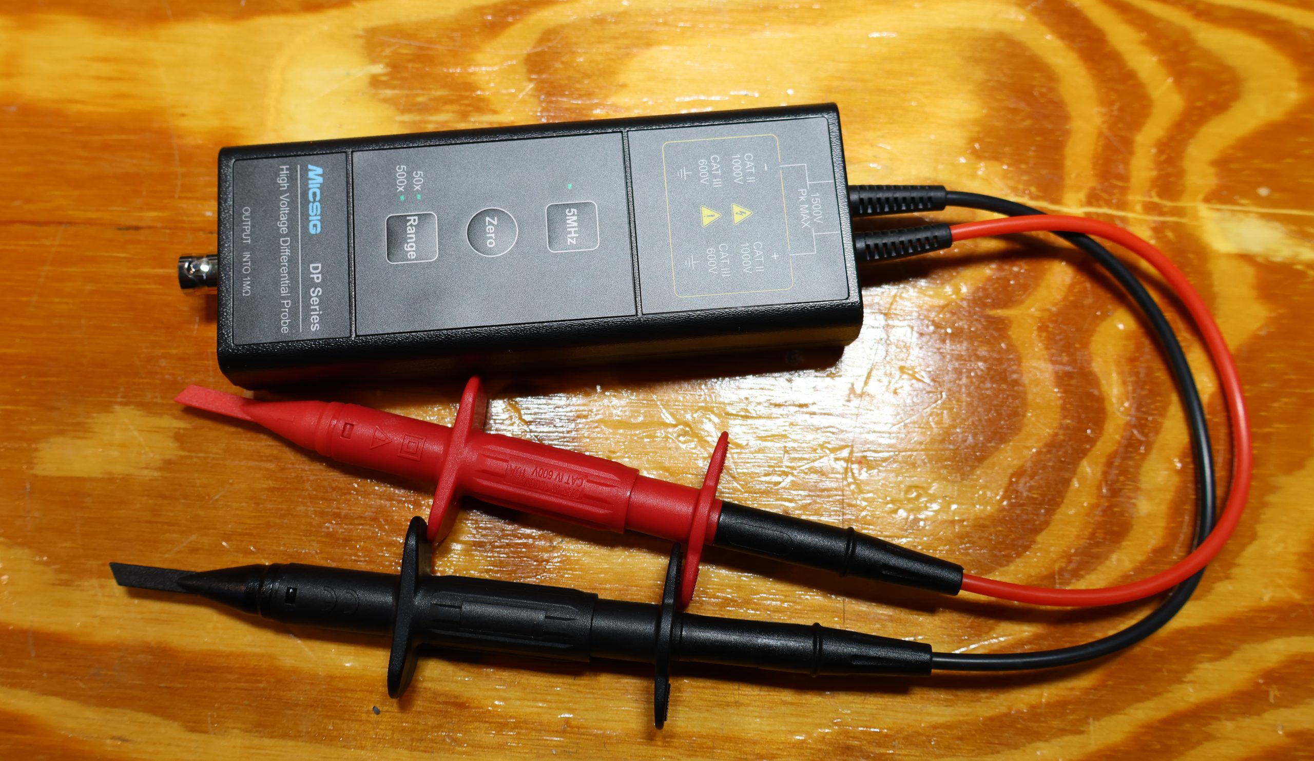
That scuffed black brick in the photo above is mine. The wooden bench under it has seen flux, solder splatter, three spilled coffees and at least one capacitor that decided to become a confetti cannon. The probe itself still works perfectly, which tells you something: it has survived my workbench, and my workbench has not been kind to it.
I bought the DP10013 after doing what every tech eventually does exactly once — clipping a scope ground lead to the “wrong” side of a bridged amplifier output and watching a beautiful blue flash where the ground clip used to be. Nobody was hurt. The amp needed a new output device. If you have not had that moment yet, congratulations, you are still on borrowed time.
Why a differential probe is not optional in audio repair
Here is the uncomfortable truth about a standard oscilloscope probe: the BNC shell, the ground clip, the scope chassis and the third pin of your wall outlet are all the same wire. When you clip that ground lead onto a node, you are not “referencing” it, you are connecting it to mains earth. If that node is not already at earth potential, something has to give, and it is usually the cheapest component in the loop — or the most expensive one, depending on how your day is going.
In audio, an alarming number of the interesting nodes are not at earth potential:
- Class-D and bridged (BTL) amplifier outputs, where neither speaker terminal is ground and both are swinging in opposite directions. A single-ended probe here is a short circuit with a handle.
- Switch-mode supplies in modern amps, subwoofer plate amps and powered monitors — primary side, mains-referenced, floating at line potential, full of the exact high-frequency hash you actually need to see.
- Emitter and source resistors for measuring bias current in situ, sitting on top of a rail rather than on the ground plane.
- Tube gear — plate loads, cathode circuits, output transformer primaries — where “measure across this” means several hundred volts above chassis.
- Anything with a floating or lifted ground, which is half of the vintage equipment that comes through my door.
The DP10013 floats the measurement completely. It looks at two points and tells the scope about the difference between them, with no galvanic path to earth on the input side. You get to keep the probe, the amplifier, the scope and your eyebrows.
What you actually get
The specs are unglamorous in the best way: 100 MHz bandwidth, 3.5 ns rise time, 50x and 500x switchable attenuation, ±1300 V maximum differential input (130 V on the 50x setting), CAT II 1000 V / CAT III 600 V safety rating, 1500 V peak absolute maximum, and CMRR around −80 dB at DC, −60 dB at 100 kHz and −50 dB at 1 MHz. It is USB powered off 5 V, which is either elegant or annoying depending on how many USB ports you have left.
The front panel is three buttons, and after two years I still think that is exactly the right number:
- Range — flips between 50x and 500x. Live with the 50x setting for most audio work; the noise floor is much friendlier.
- Zero — trims out DC offset. Press it after the probe warms up, not before, and press it again after you change ranges. This is the button everyone forgets and then blames the amplifier for.
- 5 MHz — a bandwidth limit filter, and the most underrated control on the box. When you are chasing a 100 Hz ripple problem on a rail that is also carrying switching hash, this button turns a fuzzy caterpillar into an actual waveform.
The supplied leads terminate in proper safety-rated hooks (the red and black ones in the photo), and they grip well enough to stay put on a component lead while you have both hands doing something else. Build quality is plasticky but honest — this is a $400-ish instrument doing a job that Tektronix charges four figures for, and it does not pretend otherwise.
Testing fully differential amplifiers — the Ayre V-3 case
This is where the probe stops being a safety device and starts being a diagnostic tool.
The Ayre V-3 is a fully balanced, zero-feedback design — the signal is differential from the input all the way to the speaker terminals, and both halves of the circuit are doing real work. There is no “hot” side and “ground” side in the way a conventional amp has one. If you probe one output terminal to chassis, you are looking at exactly half the story, and the half you are looking at is not the half the speaker sees.
With the DP10013 I can put red on the positive output and black on the negative output and look at the actual signal the loudspeaker receives. From there the useful measurements fall out naturally:
- Symmetry between the two phases. Probe each half against chassis in turn, then probe them against each other. A zero-feedback balanced design leans on the two halves being closely matched; drifted resistors or a tired device on one side show up as asymmetric clipping long before anyone hears it.
- DC offset behavior. Differential offset between the terminals is what matters to the driver, and that is what this probe reads directly, without me doing arithmetic on two scope channels.
- Stability and oscillation hunting. When only one half is misbehaving, a differential view separates “the amplifier is oscillating” from “my probe ground lead is a loop antenna picking up the amplifier oscillating.” That distinction has saved me hours.
- Rail and bias measurements on the same amp without re-rigging the bench or worrying about which chassis is bonded to what.
Yes, you can approximate all of this with two channels and the scope’s A−B math function. I did it for years. It works right up until it doesn’t: your common-mode rejection is now limited by how well two ordinary probes match each other, it falls apart above a few tens of kilohertz, and both ground clips are still bolted to mains earth, so the safety problem has not gone anywhere. You are doing subtraction with a fire hazard attached.
Where it disappoints
Honesty demands a few complaints:
- It is not for small signals. At 50x, low-level line stages are workable; at 500x, forget it. Tracing a moving-coil phono stage with this thing is like reading a paperback through binoculars from across the street. Keep a normal 10x probe within reach.
- Accuracy is roughly ±2%. It is a waveform instrument, not a reference meter. Do not use it to argue with a calibrated DMM.
- USB tether. No internal battery, so it needs a port or a power bank. Not a dealbreaker, but a battery version would be tidier.
- The leads are slightly stiffer than I would like and want to spring off small component legs. Minor, but you notice it on hour three.
Final verdict
The Micsig DP10013 is the least exciting purchase I have made for my bench and one of the two or three I would replace immediately if it vanished. It does not make my measurements prettier, it makes them possible and survivable — bridged class-D outputs, switch-mode primaries, floating rails, tube plate circuits, and fully differential amplifiers like the Ayre V-3 where probing to chassis simply answers the wrong question.