
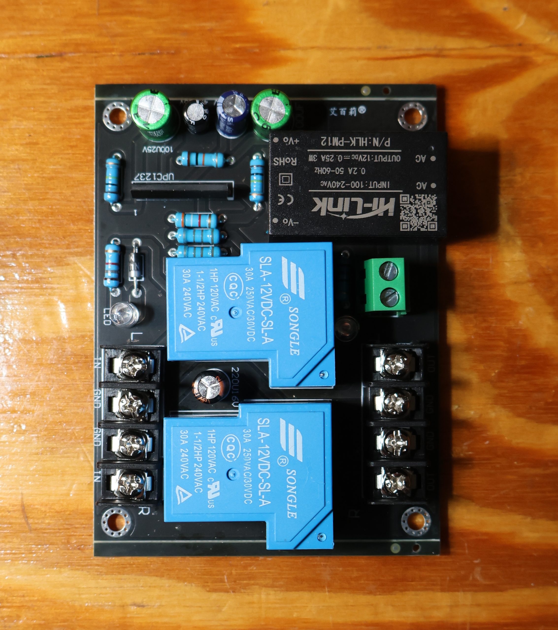
A steady share of the vintage gear that lands on my bench arrives with the same request attached to it: “while you’re in there, can you add speaker protection and short circuit protection?” It gets asked as if it were one job. It isn’t. Those are two different problems, solved by two different circuits, sitting in two different places in the amplifier. The board pictured here does one of them very well and the other one not at all — and I’d rather explain that up front than have someone believe their receiver is now bulletproof.
The short version
This board disconnects your speakers on power-up, on power-down, and when DC appears at the amplifier output. It does that reliably, for very little money, and on irreplaceable vintage drivers it is well worth the space it takes up. It does not detect short circuits, it does not detect overcurrent, it does not detect heat, and it does not know or care whether the amplifier driving it is about to destroy itself. When someone asks me for “speaker and short circuit protection,” this board is my answer to the first half of the sentence — and the second half is a separate conversation about what’s already inside their amplifier.
The long version
What’s on the board
It’s a two-channel relay protection module built around the classic Japanese-designed protection IC, the UPC1237. You can read the part number right on the silkscreen under the black tube-shaped component. The rest of the tour:
- A Hi-Link HLK-PM12 encapsulated AC/DC module — 100-240 VAC in, 12 VDC at 0.25 A out, 3 W. This is the board’s entire power supply, taken straight off the mains through the green two-pole screw terminal.
- Two Songle SLA-12VDC-SL-A power relays, rated 30 A at 250 VAC or 30 VDC. One per channel, single normally-open contact.
- A small handful of resistors setting the DC sensing network and the coil drive, a flyback diode across the coils, a 100 µF/25 V timing capacitor for the turn-on delay, a 220 µF/16 V reservoir on the 12 V rail, and an LED that tells you the relays are engaged.
That’s the whole thing. Note what is not on it, because it matters later: there is no current shunt, no sense transformer, no Hall sensor, no thermistor input, and nothing at all watching the amplifier’s output devices.
How it works
The UPC1237 does four jobs, and it does them with a single relay contact per channel as its only actuator.
1. Turn-on delay. When you power up, the 100 µF timing cap charges through a resistor and the IC holds the relays open for roughly three to five seconds. During that window the amplifier’s supply rails are stabilising, the input stages are settling, and the output nodes are doing whatever ugly transient they’re going to do. Your speakers are simply not connected while it happens. This alone is why a lot of old receivers sound “fixed” after the board goes in — the thump was never a fault, it was just an unmuted power-up.
2. DC offset detection. Each channel’s output feeds the IC through a resistor and a filter capacitor. The filter is deliberately slow, so music — even deep bass — averages out to roughly zero volts and is ignored. A sustained DC offset does not average out. When the average voltage at either input exceeds the trip threshold, in either polarity, the IC drops both relays. The threshold on a typical UPC1237 implementation lands somewhere in the region of one to a few volts at the speaker terminal, depending on the input resistor values the board maker chose. This is the headline feature: when an output transistor shorts and dumps the supply rail into your woofer, the relay opens and your speaker survives.
3. Fast turn-off. The IC also watches its own supply. When you switch the amplifier off, the 12 V rail from the Hi-Link module starts collapsing, and the IC drops the relays while the amplifier’s big reservoir capacitors are still holding the rails up. The speakers are disconnected before the amplifier has a chance to misbehave on its way down. That’s the turn-off thump gone.
4. Relay drive. Coils run off the 12 V rail with a flyback diode across them. Two SLA coils draw somewhere around 30 mA each, so with the IC’s own consumption the 250 mA supply has comfortable headroom.
What sits in series with your audio is exactly one relay contact and a short run of PCB trace. Nothing else. The board is a switch with an opinion about when to open.
Speaker protection: yes
For its intended failure mode, this design is genuinely good, and the reason is that the dangerous failure in a solid-state amplifier is almost always a DC failure. An output device shorts collector-to-emitter, one rail appears at the output, and a voice coil designed to dissipate a few watts of average power suddenly has forty or sixty volts across a few ohms of copper. That is a burning smell and a re-cone bill, and in a vintage system it may be a driver you can’t replace. A relay that opens in a few tens of milliseconds turns a destroyed speaker into a service call. On a pair of irreplaceable period-correct drivers, that trade is not close.
The turn-on and turn-off muting is the part customers actually notice, but the DC detect is the part that earns the board its place in the chassis.
Short circuit protection: no
This is where I have to disappoint people, and it’s worth being precise about why.
Short circuit protection means detecting excessive current — a shorted speaker cable, a crushed lead, a staple through the run, someone’s bare wire strands bridging the binding posts. To detect current you need something in the current path that measures it. There is nothing on this board that does. The relay contact passes whatever the amplifier chooses to push through it and reports nothing back.
Worse, the geometry is wrong even if you added sensing. A short at the speaker end sits downstream of the amplifier’s output stage. The moment it happens, the output devices are already delivering fault current. Opening a relay a few milliseconds later doesn’t save them — silicon fails faster than any mechanical contact can move. And from the DC sensor’s point of view, a dead short is a low-impedance load holding the output near zero volts: less DC at the sense input, not more. The board sees nothing wrong. It will happily sit there with the LED lit while the output stage cooks itself.
If DC does eventually appear — because the outputs finally failed short — then the relay opens. But by then the board is protecting the speaker from an amplifier you’re about to rebuild anyway.
Real short circuit protection lives inside the amplifier: V-I limiter circuits around the output stage, rail fuses, output fuses, and thermal shutdown. On vintage gear the correct answer is usually to verify the original protection circuit still works and to make sure the rail fuses are the right value and the right type, rather than to bolt on a relay board and call it done.
Fitting one to vintage gear
My rules, in order. Keep it reversible — screw terminals and spade lugs, no cut original harnesses, and the original wiring documented and photographed before anything moves. Mount on insulated standoffs, well away from the transformer, with the mains input dressed on its own path and the speaker leads kept short. Take the board’s AC feed from a switched point so that turn-off detection actually coincides with the user turning the amp off. And be honest with the owner about what changed: this is insurance, not a repair. If the amp needs a recap, new drivers, or a bias adjustment, the relay board doesn’t substitute for any of that — it just stops one class of failure from becoming an expensive one.
Test it before you close the lid
Powered up and idle, touch a single AA cell across each input to ground, both polarities in turn. The relays should drop within a second or so and re-engage after the delay when you remove it. If a channel doesn’t trip in one polarity, you have a half-working protection circuit, which is the worst kind. Re-test every few years, because the failure mode of a stuck relay is invisible from the outside.