
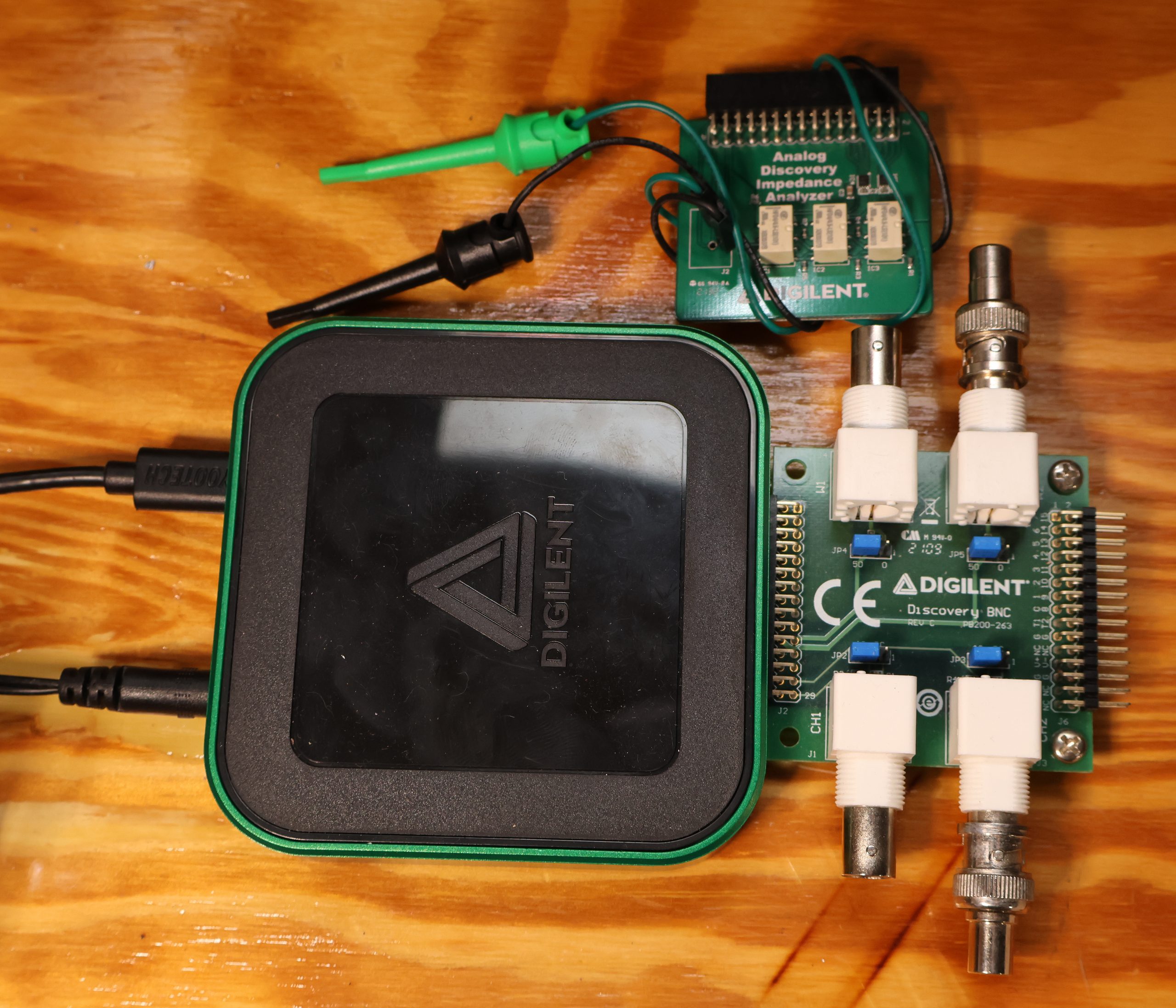
I fix audio gear for a living. Amps that hum, consoles that had a beer poured into them, tape decks whose owners insist “it only needs a belt,” and receivers from 1978 that weigh more than whoever carries them in. My bench used to be a wall of iron: a scope, a generator, a distortion analyzer, and a millivoltmeter that predates me. The Analog Discovery 3 is the size of a deck of cards, runs off a single USB-C cable, and has quietly taken over most of that wall. Not all of it. But most.
Topology first, because it explains everything else
The AD3 isn’t a scope with a USB port bolted on the back. It’s a Spartan-7 FPGA sitting in the middle of everything: two differential analog input channels, two arbitrary generator outputs, sixteen digital lines, and a pair of programmable +/-5 V rails, all bus-powered off one cable. Every instrument lives inside that same fabric on the same clock, which is adjustable from 50 to 125 MHz. Your PC is a screen and a hard drive; the measuring happens in silicon.
That sounds like a spec-sheet detail. It isn’t. Because the generator and the digitizer share a clock domain, when I sweep an amplifier the source and the receiver aren’t two instruments politely guessing about each other’s timing. They’re locked. That is what makes the Network Analyzer produce a gain and phase plot I’ll actually trust, and it’s the whole reason the Impedance Analyzer below works as well as it does.
The other topology decision that matters to me: the inputs are truly differential, plus and minus, not single-ended pretending. I can sit across an emitter resistor, or across a bridged output stage, without clipping a mains-referenced ground onto the wrong node and turning a repair job into a fireworks display. Anyone who has done that once remembers the smell.
The specs, briefly, in audio terms
- 14-bit converters in both directions, 125 MS/s, 32K samples per channel (64K on a single channel)
- +/-2.5 V and +/-25 V input ranges; 9 MHz analog bandwidth on the flywires, 30+ MHz with the BNC adapter
- Two generator channels, +/-5 V, 14-bit, with sweeps and modulation
- Programmable +/-5 V supplies at up to 800 mA, which will happily power a phono board on the bench
- 16 digital channels with protocol decode, including I2S
For audio, 125 MS/s is roughly 2,800 times oversampling of a CD. I run this thing at a fraction of its athletic ability all day, which is exactly why it behaves so well at 1 kHz. The 14-bit converters look thin next to a 24-bit audio analyzer — about 85 dB of raw dynamic range on paper — but FFT processing gain pushes the per-bin noise floor well below that, so harmonics around -100 dBc are visible and repeatable. It is not an Audio Precision. You are also not chasing 0.0005% THD on a Twin Reverb that came in smelling of cigarettes.
The scope, which is the part I use every single day
Crossover distortion is the headline act: sine into the input, probe across the load, zoom the zero crossing, and the notch is right there on screen while I turn the bias pot. The FFT view settles the eternal hum-versus-buzz argument in about four seconds: a clean line at the mains fundamental is one problem, a picket fence of harmonics marching up the screen is another entirely, and knowing which before you start unsoldering saves an hour. Two differential channels plus XY mode gives me tape head azimuth without a dedicated alignment box. Persistence catches the intermittent that only shows up when you tap the chassis, which is, of course, the only time it ever appears.
And because the logic analyzer sits right there on the same clock, when a modern powered speaker comes in dead I can check whether the DSP is even getting I2S data before I start suspecting the amp module.
The Impedance Analyzer is the tool I didn’t know I was missing
If you do anything with speakers, this one instrument justifies the purchase on its own. There’s no extra box: the generator drives the part under test through a reference resistor, the two scope channels sit across the resistor and across the device, and the software sweeps frequency and solves for complex impedance at every step. Pick a reference resistor near what you’re measuring — about 100 ohms for an 8 ohm driver keeps the drive close enough to constant current — and you’re done. Digilent sells an adapter that relay-switches reference resistors, which is tidy, but a resistor and clip leads works too.
What comes back is magnitude and phase against frequency, plus series and parallel R, L and C, ESR, Q and D, and a Nyquist plot if you like your data in circles. In audio terms:
- Drivers: the full impedance curve gives you DC resistance, free-air resonance and voice coil inductance in one sweep. Add a known mass or a known box and you’re into Thiele-Small territory without a dedicated jig.
- Driver diagnosis: a resonance peak that has drifted low means a tired suspension; a ragged curve usually means a rubbing coil. Both show up on the plot before you can clearly hear them.
- Crossover parts: measure the actual inductance and DC resistance of that air-core coil and the real capacitance and ESR of the cap before soldering them in. Parts land 10% from their labels often enough, and 10% moves a crossover point somewhere you didn’t intend.
- Finished systems: sweep the whole speaker and you see the impedance minimum — useful before handing an amplifier a 2.6 ohm dip it wasn’t expecting — and confirm the crossover got assembled the way the drawing said.
- Iron: primary and secondary inductance on output transformers, and shorted turns that announce themselves as inductance which has mysteriously collapsed.
- Headphones and cartridges: impedance and inductance, so loading decisions get measured rather than argued about on forums.
It is a small-signal measurement, so it won’t tell you what a driver does when it’s hot and moving — but for repair and crossover work it’s the fastest honest answer on the bench.
The Audio Analyzer Suite is the part that makes this an audio tool
I need to be straight about this. WaveForms, the bundled software, is excellent and it is general-purpose. It gives you a scope, a generator, an FFT, and a lot of manual labor. The Audio Analyzer Suite is what turns a general-purpose instrument into an audio instrument: THD+N versus frequency, THD+N versus power, intermodulation distortion, automated frequency response sweeps, input and output impedance, and a spectrum analyzer with the generator on the same screen, all reported in the units and formats an audio job actually asks for.
The value is automation of tedium. Without it, characterizing a preamp means hand-stepping the generator, reading a cursor, typing a number into a spreadsheet, thirty times over, then finding you fat-fingered the 6.3 kHz entry. With it, I hit run and the whole THD+N versus frequency curve draws itself while I make coffee, and the customer gets a before-and-after plot that looks like it came off equipment worth twenty times as much. Without the Suite, the AD3 is a very good scope and generator you have to drive by hand. With it, it’s an audio analyzer. That software roughly doubles what the hardware is worth to me, which is a strange thing to say about a free community add-on, and it does mean tracking down a working copy and a compatible WaveForms version is a small adventure of its own.
The elephant on the bench: what about the QA403?
Every time I mention the AD3 in an audio context, someone asks why I don’t just use a QuantAsylum QA403. Fair question, and the honest answer is that they aren’t really competing for the same job.
What the QA403 does better:
- Distortion floor, by a mile. It’s a purpose-built audio analyzer with 24/32-bit converters running at up to 192 kS/s, a noise floor down around -115 dBV and loopback THD in the same neighbourhood. The AD3’s 14-bit front end, even with FFT gain working in its favour, runs out of room long before that. If you need to prove an amplifier is genuinely clean rather than merely not broken, the QA403 measures it and the AD3 measures its own noise.
- Isolation. The QA403’s audio ground is galvanically isolated from USB ground. On an audio bench that is worth actual money, because the ground loop you can’t see is the one adding the 60 Hz line to every measurement you take. The AD3’s differential inputs help, but the device still shares a ground with your laptop. However that could be easily overcome with a galvanic isolation device from Amazon ($30 gets you there)
- It connects to real audio gear without ceremony. Balanced differential BNC in and out, AC-coupled high-impedance inputs, eight input ranges reaching 40 V RMS, and outputs that will swing 8 V single-ended or 16 V balanced through real attenuators. You can hang it on a power amp output at sensible power levels without building a divider first, and DC offset on the device under test doesn’t upset it.
- The software is audio-first out of the box. Swept THD and THD+N against frequency and level, SNR, gain, crosstalk, IMD, plus a REST interface for scripting the whole thing. No hunting through old forum threads for a community add-on.
What the AD3 does better:
- It’s an oscilloscope, and the QA403 isn’t. This is the big one for repair. Triggering, time-domain waveforms, persistence, catching the intermittent when you flex the board — none of that exists on an analyzer that only speaks in spectra. Most of my day is diagnosis, not certification.
- Bandwidth. The QA403 stops just short of 100 kHz. Class-D switching residual, an output stage oscillating at 2 MHz, a switching supply misbehaving at 65 kHz, a tweeter protection circuit ringing — those live above the audio band, and that’s exactly where an audio analyzer goes deaf and a scope starts being useful.
- DC coupling. Bias voltages, DC offset at the speaker terminals, sagging rails, a drifting servo. The QA403’s AC-coupled inputs won’t tell you any of it; the AD3 will, on the same probe you’re already holding.
- Everything that isn’t audio. Sixteen logic channels with I2S and I2C decode for digital sources and control busses, a pattern generator, a network analyzer good to megahertz, and a pair of programmable +/-5 V supplies that will power a board on the bench while you poke at it.
- Price and pocketability. It costs a couple of hundred dollars less and it goes to house calls.
The short version: the QA403 is the instrument you buy to prove something is good. The AD3 is the instrument you buy to find out why something is bad. If your work is characterising finished designs and publishing numbers, buy the QA403 and don’t look back. If your work is fixing things that arrive broken, the AD3 answers more questions per day — and if you can eventually justify both, they complement each other almost perfectly.
What it can’t do
- +/-25 V input means real power amp outputs need a dummy load and attenuation. Do not learn this the expensive way.
- The BNC adapter is technically optional and practically mandatory.
- The generator’s own residual distortion sets your floor, so genuinely low-distortion work still wants an external notch filter.
- Your screen is a laptop, so your instrument occasionally reboots for updates at inconvenient moments.
Final verdict
For audio repair, the Analog Discovery 3 is a fantastic value on my bench, full stop. It replaces a scope, a generator, a sweep rig, an impedance bridge and a distortion analyzer, and travels to on-site jobs in the same bag as my soldering iron. It will not out-measure a real audio analyzer, and it shouldn’t have to. Buy it, budget for the BNC adapter, and treat the Audio Analyzer Suite as a required part rather than an accessory — and if you build or repair speakers, the Impedance Analyzer alone will pay for the thing. Without the Suite it’s a clever gadget; with it, it’s the instrument I reach for before anything else. And if a dedicated audio analyzer eventually joins it on the bench, the AD3 doesn’t get retired — it just stops being asked to do the one job it was never built for.