
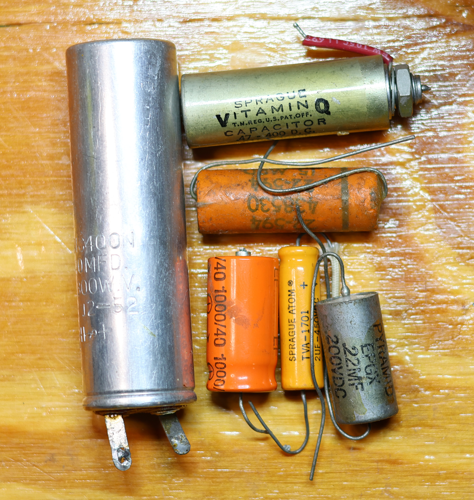
Somewhere between “if it works, don’t touch it” and “shotgun every capacitor in the chassis” there is an actual engineering answer. Recapping is not maintenance you perform on a schedule like an oil change. It is a repair you perform on evidence. The trouble is that most of the evidence is invisible from the top of the chassis, and the wrong decision costs you either a set of output tubes or the originality of a piece that was fine as it was.
Here is how I decide.
Three jobs, three failure modes
A vintage chassis holds capacitors doing completely different work, and they fail in completely different ways.
Filter capacitors (electrolytics in the power supply) live under ripple current and heat. They dry out. Capacitance falls, ESR climbs, and the symptom is hum, sag under load, or motorboating.
Coupling capacitors (paper, paper-in-oil, film) pass audio between stages while blocking DC. They fail by becoming slightly conductive. The symptom is not hum — it is a control grid that has drifted positive, an output tube running red-plate hot, and a bias reading that will not stay put.
Cathode bypass, tone stack, and timing capacitors are a mixed bag: small electrolytics that dry out, plus ceramics, silver micas, and polystyrenes that essentially never fail.
Treating all three as one job is why “full recap” jobs so often sound worse than the original.
The always-replace list
Some parts get changed regardless of how well the unit is playing:
- Any electrolytic showing bulge, vent, crust, or a leaked electrolyte halo. No testing required.
- Line-filter X and Y capacitors, especially RIFA. These crack, absorb moisture, and fail spectacularly. Every 70s–80s receiver with a translucent yellow-brown epoxy block across the mains gets new safety-rated parts.
- Black Beauty, Bumblebee, and wax-paper coupling caps in tube gear. Not because of tone mythology — because after 60 years they leak DC, and I have never measured a good one.
- Surface-mount electrolytics in late-80s and 90s equipment. They leak onto the board and eat traces.
- Anything in a piece that has sat unpowered for a decade or more and pulls current on a variac.
The leave-it-alone list
- Silver mica, ceramic disc, polystyrene, and polypropylene film. These do not age in any way you can measure.
- Orange drops, Mallory 150s, and similar polyester parts installed during a previous service. They are fine and they are twenty years newer than you think.
- Original coupling caps that test clean for leakage. Rare, but they exist — some Sprague Vitamin Q and later mylar parts pass.
- Large filter cans that measure in spec, in gear that is not going into daily service. A working multi-section can with correct ESR is worth more than a bank of hidden modern caps under the chassis.
ESR testing that means something
An ESR meter is the fastest triage tool on the bench, and the most commonly misread.
The mistake is looking for an absolute threshold. ESR scales roughly inversely with the capacitance-voltage product, so a 4700 µF/50 V rail cap should read 0.02–0.05 Ω, a 470 µF/35 V part around 0.05–0.15 Ω, a 10 µF/450 V axial 1–4 Ω, and a 1 µF/50 V electrolytic 5–15 Ω. That last one is not defective. Small low-voltage electrolytics are naturally high-ESR, and half the “bad caps” reported on forums are perfectly healthy 1 µF parts measured against a 0.1 Ω expectation.
The reliable method is comparative. Buy one new capacitor of the same value and voltage rating, measure it, and use that as your reference. Three times the new part’s ESR is suspect; ten times is dead. No table required.
Two cautions. In-circuit readings are only trustworthy when they are bad — parallel paths, transformer windings, and semiconductor junctions all read low and can hide a failing part. Lift one leg before you condemn or exonerate anything marginal. And ESR alone is an incomplete picture: a capacitor can show excellent ESR while having lost 60% of its capacitance. Check both. On an LCR meter, measure large electrolytics at 100 Hz, not 1 kHz, or the numbers will not mean what you think.
The test that actually catches bad coupling caps
ESR is nearly useless on coupling capacitors. Leakage is the whole game, and leakage only appears at working voltage — which is exactly why a capacitor that reads “OK” on a handheld meter at 3 V can still be feeding 40 V of DC into a grid.
The five-minute in-circuit version: power the amp up, let it warm, and measure DC from the following stage’s control grid to ground with a 10 MΩ input DMM.
- Cathode-biased stage: grid should read 0.0 V. Under 20 mV is normal drift. Over 100 mV, replace. Over 1 V and the output tube is already being damaged.
- Fixed-bias stage: the grid should sit at the bias voltage and stay there. A reading that creeps less negative over ten minutes is a leaking coupling cap, not a bias pot.
The bench version, for parts out of circuit: series a 1 MΩ resistor with a variable HV supply, ramp to the cap’s working voltage, and measure the voltage across the resistor to get leakage current. A healthy modern film cap leaks in the nanoamp range. Anything reading microamps at working voltage goes in the bin.
Three worked examples
Dynaco ST-70. The quad can filter cap is usually tired but the real hazard is the driver board’s coupling caps to the EL34 grids. Measure grid DC first. If it is clean and the amp is quiet, the can may well stay; if there is hum and the can measures 5× reference ESR, replace it — but respect the 5AR4’s ~60 µF first-capacitor limit rather than “upgrading” to 100 µF and stressing the rectifier on every turn-on.
Fisher 500-C. Wax-paper couplers throughout, and they will be leaking. Replace them, replace the filter can, and check the selenium rectifier in the bias supply — a failing bias supply produces the same red-plating symptom and gets misdiagnosed as a cap problem constantly.
Pioneer SX-780. The RIFA line cap goes on principle. The big main filters are frequently still in spec — measure them. The parts that are actually dead are the small 1–10 µF electrolytics on the tone and phono boards, which cause thin bass and channel imbalance and cost almost nothing to change.
The workflow
Bring it up on a variac with a dim-bulb limiter and watch current draw. Photograph everything before you unsolder anything. Measure grid DC on every tube stage. ESR-and-capacitance the electrolytics against a new reference part. Then change only what failed a test — and log the readings, because the next person to open the chassis deserves better evidence than you had.