
Some projects start with a plan. This one started with a dead amplifier and a decision not to fix it.
I picked up a broken Emotiva BasX A-500 — the five-channel home theater workhorse. My first instinct was to repair it. But the honest truth is that the A-500 was never a great-sounding amp to begin with. It’s competent, it drives five channels, and it has a genuinely nice linear supply behind it, but nobody has ever described it as musical. Spending a weekend chasing a fault to end up with an amp I didn’t want to listen to seemed like a poor trade.
So the A-500 became a donor.
Original Emotiva BasX A-500 specs (for reference):
| Channels | 5 |
| Power (2 ch driven, 8Ω) | 110 W RMS, 20 Hz–20 kHz, THD < 0.1% |
| Topology | Class A/B, linear power supply |
| Dimensions | 17″ W × 4″ H × 15.5″ D |
| Weight | 26.5 lbs |
What stayed, what went
The teardown split cleanly into two piles.
Kept:
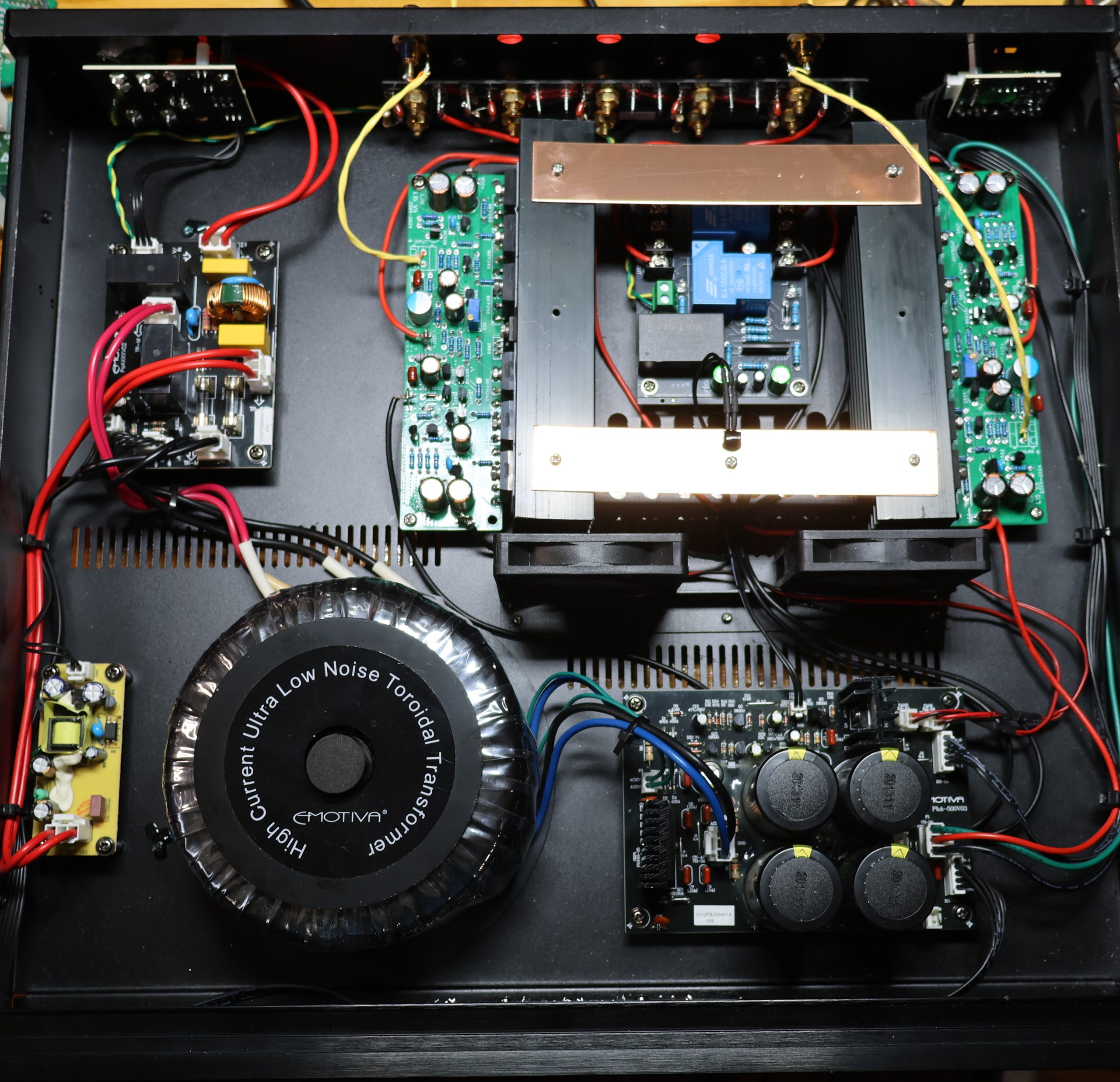
- The chassis. This was the single biggest reason to do the project this way. A 17″-wide, 4″-tall, 15.5″-deep steel-and-aluminum enclosure with proper vents, a brushed front panel, and IEC inlet already drilled — buying an equivalent DIY chassis costs real money and this one was already sitting in front of me. The internal volume is close to ideal for a two-channel build: enough room for the transformer, generous space around the boards, and depth for airflow.
- The five front-panel LEDs. The A-500 has five of them, one per original channel. They’re a fun bit of visual character and I saw no reason to lose them just because the amp only has two channels now. (TBD: describe how the LEDs ended up wired — all five off one rail, sequenced, split between channels, etc.)
- The toroidal transformer. Big, quiet, and — crucially — already the right voltage.
- The power supply board. Rectification, filter caps, and the fan control circuit all live here.
Removed:
- The original amplifier modules. The entire reason for the project.
- The original speaker protection board. Tied too closely to the old amp topology to be worth adapting.
The amp boards: LJM L15 MOSFET
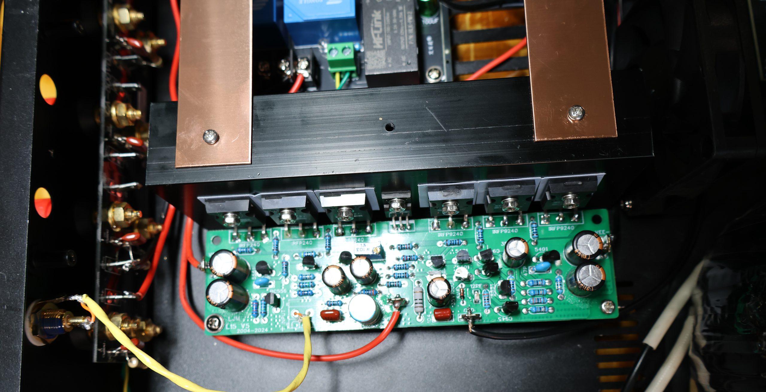
I went with the L15 MOSFET board, which has a long and well-earned reputation in DIY audio circles. It’s one of those designs people keep coming back to — a lateral-ish approach to a vertical-MOSFET output stage that manages to sound smooth rather than clinical.
L15 MOSFET board specifications:
| Topology | Class AB, MOSFET output stage |
| Output devices | 3 × IRFP240 (N-ch), 3 × IRFP9240 (P-ch) per channel |
| Driver | IRFS610B |
| Power output | 150 W into 8Ω / 300 W into 4Ω / 600 W into 2Ω @ ±55V |
| THD | < 0.02% at 150 W into 8Ω |
| SNR | > 97 dB |
| Frequency response | 5 Hz – 250 kHz (−3 dB) |
| PCB size | 150 × 40 × 26 mm |
| Configuration | Mono blocks (two used for stereo) |
The board’s rated maximum supply is ±70V. The Emotiva’s supply delivers ±50V, which is close to the top of the board’s range without running it at the edge — a genuinely lucky match, and one of those moments where a salvage project stops feeling like a compromise and starts feeling like it was meant to be. No transformer swap, no rail regulation, no rewinding. The existing supply just plugged in.
Output power in practice: with ±50V rails sagging under load and the usual few volts of headroom lost across the MOSFET source followers, real-world clean output lands around 100 W into 8Ω — a good deal less than the board’s ±70V/150W rating, but with the full weight of the Emotiva’s linear supply behind it and plenty of thermal margin on the devices.
Setting the bias — the boards arrived underbiased
This turned out to be the most important thing I did to the amp, and it’s the step I’d tell anyone building with these boards not to skip.
The L15s arrive assembled and nominally ready to run, and it’s tempting to treat them as plug-and-play. They aren’t. On first power-up I put the amp on a current meter and probed the gate-source voltage on the output MOSFETs — and the numbers made it immediately clear the boards were not biased properly. V_GS was set to about 2.5V.
That’s a problem, because 2.5V sits right at the bottom edge of the IRFP240/IRFP9240 gate threshold window. At that setting the output devices are barely turned on at idle — effectively running the stage closer to Class B than Class AB. The symptom is crossover distortion: the handoff between the N-channel and P-channel devices around the zero-crossing isn’t smooth, and it shows up audibly as a hard, slightly grainy quality that’s worst at low listening levels, exactly where the signal spends most of its time near zero.
I raised V_GS to 3.3V, which brought idle current up to 50 mA per amplifier. At ±50V rails that’s about 5W of standing dissipation per channel — enough to put the output devices comfortably into conduction and keep them there through the crossover region, without pushing anywhere near the thermal limits of the heatsinks. The amp now sits warm at idle rather than cold, which is exactly what you want to see: a Class AB MOSFET amp that’s stone cold at idle is telling you it isn’t biased.
A few notes if you’re doing the same:
- Let it warm up before you set anything final. MOSFET bias drifts with temperature, and a number set on a cold board won’t be the number you have twenty minutes later. Set it, let the amp come up to temperature, come back and re-check.
- Measure the current, don’t just trust the voltage. V_GS is the adjustment; idle current is the result you actually care about, and it’s what tells you whether you’ve landed in the right place. For example one channel had 50 mA current at 3.3 V, but the other needed to go to 3.4 V to achieve the same current.
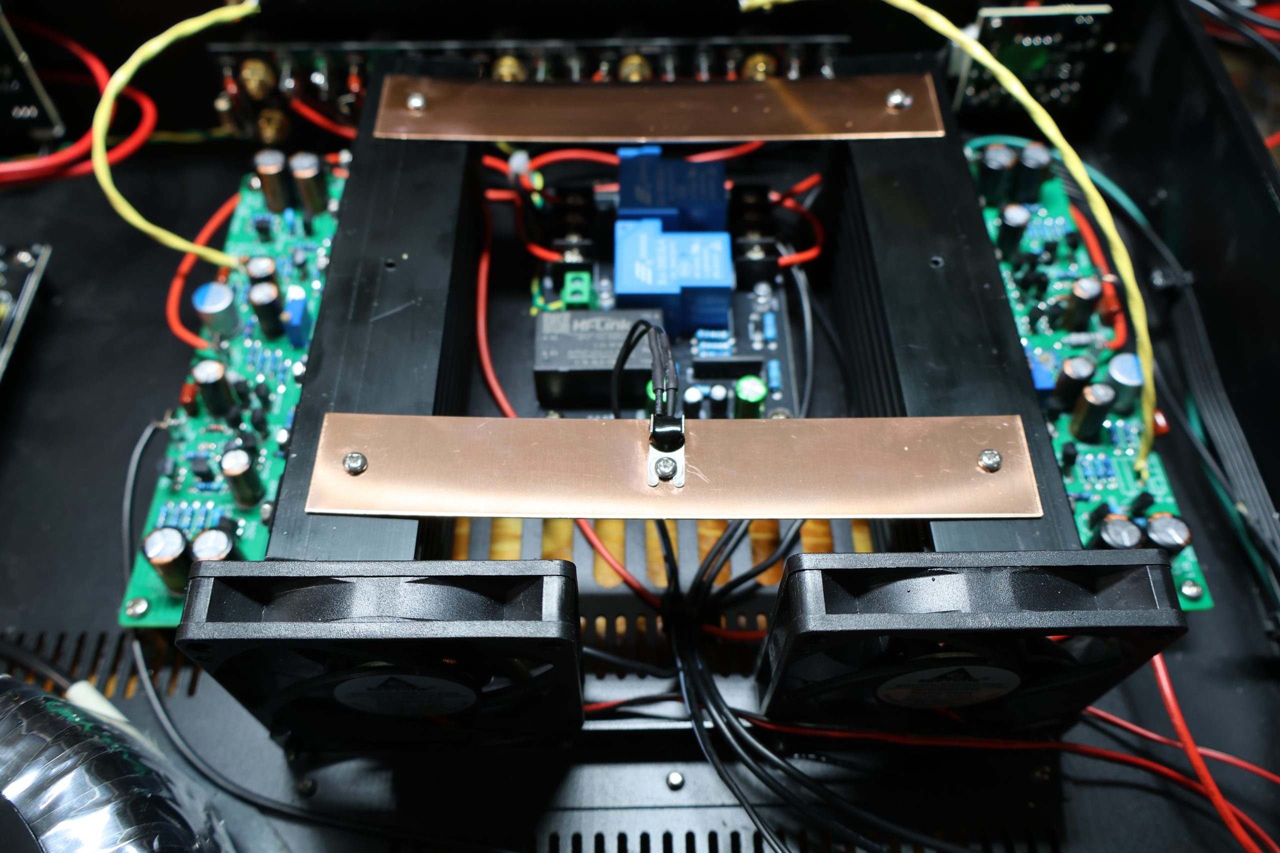
- The copper strip coupling the two heatsinks earns its keep here too — with both channels sharing a thermal mass, their bias drifts together instead of independently. It also holds the thermistor that controls the fans.
Worth saying plainly: this single adjustment is responsible for a large share of how good the amp ended up sounding. The smoothness and the lack of grain in the upper mids that I describe below are, I’m fairly sure, mostly the difference between a properly biased output stage and one running on the factory setting.
No offset trimpot — so the matching had better be good
One more thing worth knowing before you buy these boards: the L15 has no DC offset trimpot. There is a bias adjustment, but there is no second pot to null the DC sitting at the speaker terminals. On a lot of amplifier designs that’s your safety net — whatever mismatch exists between devices, you dial the offset out by hand at the end.
Not here. With no trim available, the offset you get is whatever the device matching gives you, and that puts the whole burden on the board being built with closely matched devices. It’s a design choice that’s either a virtue or a liability depending entirely on who assembled your board — a well-matched set lands near zero with no intervention, and a sloppy one leaves you with an offset you simply cannot fix without swapping parts.
Happy to report mine came out well: measured DC offset was 3–5 mV at the outputs after warm-up. That’s an excellent result — low enough to be irrelevant to any speaker you’d plausibly connect, and a good sign that the devices on these boards were genuinely matched rather than pulled from a bin. For context, anything under about 25 mV is generally considered fine, and plenty of well-regarded commercial amps ship with more offset than these boards have.
Do check it, though, before you connect speakers for the first time. If your boards came out badly matched, the absence of a trimpot means you want to find that out with a meter across the output terminals — not with a woofer attached.
Cooling: reusing the fan circuit
The A-500’s fan control circuit lives on the power supply board, which meant it survived the teardown intact. Rather than let it go to waste, I built the thermal path around it.
The two L15 boards are mounted with a copper strip bridging their heatsinks, and the fan circuit’s thermistor sits on that strip, between the two amps. This does two useful things at once:
- It thermally couples the two channels, so both amps share heat rather than one running hot while the other loafs — helpful for channel-matched bias drift.
- It gives the thermistor a single sensing point that genuinely represents the state of both amplifiers, so the fan responds to actual total dissipation instead of one arbitrary channel.
And the fans turned out to matter more than I expected, because the heatsinks the L15 boards ship with are badly undersized. They’re small extruded aluminum sinks — fine for a bench test, fine for a board being run gently, and not remotely adequate for two channels putting out 100W each in a closed chassis. Left to natural convection alone they’d have been the limiting factor of the entire build, and I’d have been looking at buying proper sinks or cutting the chassis for external ones.
Forced air changes that math completely. Even modest airflow across a small heatsink cuts its effective thermal resistance dramatically — a sink that’s marginal in still air becomes comfortable with a fan on it, because natural convection is by far the weakest link in the chain from die to room. Inheriting a working fan circuit meant the stock heatsinks went from “these need to be replaced” to “these are fine,” which saved both money and a lot of fabrication.
There’s a second benefit that ties back to the bias adjustment: stable temperatures mean stable bias. MOSFET idle current drifts with junction temperature, so an output stage that swings through a wide temperature range also swings through a wide range of quiescent current. Keeping the heatsinks in a narrower thermal band keeps the 50 mA idle setting closer to 50 mA in actual use, rather than being a number that’s only true at one particular moment.
The result is that the amp runs fanless and silent at normal listening levels and only spins up when it’s actually working. Reusing the original circuit meant no new fan controller to design, no new supply rail to derive, and no additional failure point — and it rescued the one genuinely weak component in the L15 package.
Speaker protection: UPC1237 module
For speaker protection I used an off-the-shelf UPC1237-based module (this one on Amazon). The UPC1237 is the classic chip for the job and handles the three things that matter:
- Turn-on delay — keeps the thump out of your speakers while the rails come up and the amp settles.
- DC offset detection — disconnects the speakers if an output stage fails and dumps DC into them.
- Fast turn-off mute — drops the relays the moment mains power is lost, before the rails collapse and the outputs misbehave.
The thing that made this particular module worth choosing is its built-in 85–265V AC power supply. Most UPC1237 boards need a low-voltage AC or DC feed derived from a separate transformer winding — which, in a salvage build where the transformer’s secondaries are already spoken for, is exactly the kind of annoying problem you don’t want. This board takes mains directly and generates its own 12V. It wires in with a mains connection, the speaker outputs in, and the speaker terminals out. That’s it.
Other build details
The original A-500 speaker terminals stayed. They’re solid, properly spaced five-way binding posts, and there was nothing to gain by replacing them. The protection module’s relay outputs wire straight to them.
The back of the amp ended up a split decision — one half replaced, one half kept.
The RCA jacks had to go. All five of the A-500’s inputs were mounted on a single dedicated PCB, which is a sensible way to build a five-channel amp on a production line and an actively unhelpful one for a two-channel rebuild. It’s an all-or-nothing assembly: you can’t cleanly pull two jacks off it and leave the rest, and keeping the whole board means keeping a run of PCB trace between your input connector and your amplifier board for no good reason. The jacks themselves were also plainly lower quality — thin plating, the sort of loose grip on a plug that gets worse with every insertion.
So I replaced them with standard gold-plated RCA jacks, individually mounted to the chassis. Nothing exotic and nothing expensive — the point isn’t boutique connectors, it’s a solid mechanical grip on the plug, a contact surface that won’t corrode, and the freedom to run a short shielded lead directly from each jack to its amplifier board instead of through somebody else’s PCB.
How it sounds
This is where the project justified itself.
The finished amp is very good. Bass is tight and controlled — the kind of grip that makes you notice bass lines you’d been hearing as a general low-frequency event. It’s musical in the way that matters: it doesn’t editorialize, it doesn’t smear, and it doesn’t get congested when the music gets dense. Smooth and transparent, with none of the slightly hard, grainy quality the original Emotiva had in the upper mids.
Roughly 100 W per channel into 8Ω from the salvaged supply, which is more than enough for any sane listening level in a normal room.
Was it worth it?
The economics are hard to argue with. A broken multichannel amp — the kind that sells cheap precisely because nobody wants to fix one — gave up a quality toroidal transformer, a working linear supply with a fan controller already on it, and a chassis that would have cost more than the entire rest of the project. Add two L15 boards and a $15 protection module, and the result outperforms the amp it came from by a wide margin.
The broader lesson: when you’re eyeing a broken amp, evaluate the parts, not the product. A mediocre amplifier can still be a great collection of components. The A-500 wasn’t worth repairing. It was absolutely worth harvesting.